VerticalProfileOperator Class
Creates a vertical profile of terrain or vector data.
NuGet/Assembly: Carmenta.Engine.5.17.0.nupkg (in the CEOperators assembly)
Syntax
public class VerticalProfileOperator : OperatorRemarks
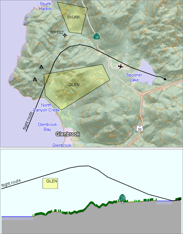
There is a sample map configuration vertical_profile.px that uses a VerticalProfileOperator to show a vertical profile in the terrain east of Lake Tahoe.
Introduction
This operator generates a vertical profile of 3D data from ElevationInput, along a given route from RouteInput. The 3D data may be points, lines, polygons and elevation rasters, but not meshes. The route from RouteInput should be a single line feature, and is usually read from a MemoryDataSet.
The operator can also take rasters containing land-cover types and their heights above ground, via the special inputs LandCoverInput and LandCoverHeightInput.
 |
By default, the profile contains only the 3D data that is directly below or above the route, and optionally the route itself. This default setting is used in the example above, so the profile shows
the elevation of the ground and land cover directly below the route (the colors depend on the type of land cover),
a road line at the point where it intersects the route,
water polygons and airspace polygons where they intersect the route.
The 3D point features that are slightly beside the route - two obstacles, a waypoint, and the aircraft - do not appear in the profile. The blue names of water areas are also missing because they are attributes not of the lake polygons, but of points from a separate text dataset.
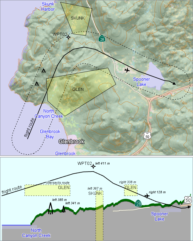
By using a positive MaxDistance, you can let the profile show data farther from the route:
 |
In this example, the MaxDistance = 500 m defines a buffer zone around the route, as shown in the 2D map by means of a BufferZoneOperator. Now the profile shows additional features:
the 3D points inside the buffer zone,
the airspace polygons where they intersect the buffer zone,
the water names that are attached to points inside the buffer zone.
Also, the features that were displayed previously have a new appearance:
the roads appear as lines, where they intersect the buffer zone,
the ground and trees show the highest elevation along a line perpendicular to the route within the buffer zone.
The vector features in the profile have an attribute, vpopDistanceToRoute, giving the (signed) horizontal distance to the route, which was used to generate the italic labels above.
The sample configuration vertical_profile.px is designed in this way, and can display the narrow profile and the buffer-zone profile at the same time.
Details
The route defines the position of a vertical surface, which consists of a sequence of vertical plane segments, one for each segment of the route. You may think of the route as defining a fence that is infinitely high (and deep), and the operator paints the fence with a scene from the 3D world coming from ElevationInput. The various kinds of input features cause different kinds of output features:
Point. A 3D point from ElevationInput, within MaxDistance from the fence, will normally generate a corresponding point on the fence surface, with the height taken from the z coordinate of the 3D point. More generally, the 3D point can be interpreted as having a vertical extent from a minimal to a maximal elevation. The minimal elevation is then specified via the BottomElevation that can depend on the 3D point attributes, but if this evaluates to its default value, the minimal elevation will be the z coordinate. The maximal elevation is specified via TopElevation in the same way. If the minimal elevation differs from the maximal one, the output feature will be a vertical line instead of a point.
Line. A 3D line from ElevationInput will first be clipped by a buffer zone that extends MaxDistance horizontally from the fence. Only the line parts that are inside the buffer zone will generate output lines. If the MaxDistance is zero, then clipped parts are usually just the points where the 3D line intersects the fence, so the output will be points instead of lines, although a 3D line that coincides with a part of the fence can still generate output lines. Normally, the z coordinate of each node in the input line is used as the elevation of the corresponding node in the output feature. However, as for input point features, it is possible to fetch a minimal and/or a maximal elevation for each input line from its attributes; if this is done, the output features will be polygons that extend down to the bottom elevation, and/or up to the top elevation (or, if MaxDistance is zero and the 3D line passes through the fence, the output can be a vertical line segment).
Polygon. For a polygon feature, it is seldom useful to have a distinct elevation (z coordinate) at each node, since it would be ambiguous how to interpolate the elevation in the interior. In aeronautics, one uses 3D volumes known as airspaces, whose horizontal extent is given by a 2D polygon while the vertical extent is given by two numbers: the lower and upper vertical limits. The VerticalProfileOperator assumes that each polygon feature from ElevationInput has a lower and an upper limit that can be retrieved via BottomElevation and TopElevation. In the unlikely case that these are evaluated to their absurd default, the lower (or upper) limit is instead taken from the smallest (or largest) z coordinate of the polygon. When the lower and upper limits are known, the polygon is clipped by the buffer zone that extends MaxDistance horizontally from the fence. Each remaining part generates a rectangular polygon feature in the output.
Elevation raster. A raster of ground elevations will generate a line on the fence, normally where the fence touches the ground. If Close is True, the raster will also generate a polygon below the ground level (or above the ground, if ClosingHeight is higher than the ground). Raster cells within MaxDistance from the fence can also affect the result. Note that input rasters that describe land cover are handled in a special way; see LandCoverInput.
Volume-encoding rasters. Apart from vector data and ordinary elevation rasters, the ElevationInput can also give the special volume-encoding rasters that can be produced by a LineOfSightOperator or an AirspaceCoverageOperator and represent viewshed volumes. The results from these will always be polygon features representing where the fence cuts through the volumes.
The route itself. When the route represents a 3D flight route, you can get an output line that corresponds to the route by letting OutputRoute be True. An alternative way would be to make the route appear also as an input feature from ElevationInput, but this would be less efficient. However, the alternative can be used if each segment of the route has its own set of attributes that should affect the output; maintaining the different sets of attributes would then require that each route segment appears as a separate input feature from ElevationInput. Of course, another possibility is to use some application code to calculate how the route segments shall appear in the profile View, and then store the results in a MemoryDataSet, whose features can be sent to the profile View without passing through a VerticalProfileOperator.
Some care may be needed if the fence segments are very long, and the coordinates of the input are longitude and latitude. Because the operator works in the plane geometry of its input, and a very long straight line in the LongLat geometry does not correspond to a great-circle route on the round Earth. If this is a problem, you can insert intermediate points on the route. For example, you can insert a ScriptOperator in your operator chain for RouteInput, with the following code:
feature.geometry = feature.crs.route( feature.geometry, LineType.GreatCircle, False, 10000, 100)
Input coordinates
You can specify the ElevationUnit, which is the vertical length unit of all input features (z coordinates of vector data, cell values of elevation rasters).
The operator requires all features coming from ElevationInput and RouteInput to be expressed in the same Crs. If they are not, you have to reproject them with a ProjectOperator. It is usually fastest to reproject the vector data (the route and other vector data in the input) to the same CRS as the raster data. But if the route has long segments, then the reprojection may change exactly which raster cells that the route passes through. To get more control over this, you must insert intermediate points on the long route segments. How you should do this, depends on what the long route segments really represent. For example, if the long route segments shall represent straight line segments in their original Crs, then you can let your ProjectOperator get a ProjectParameters object, in which you set edgesToSegmentize = All and an appropriate edgeLengthMax. See also the great-circle example above.
The special raster features that may come from LandCoverInput and LandCoverHeightInput are allowed to be expressed in a different CRS, and it should be more efficient to let the operator handle the coordinate transformations than to insert a ProjectOperator to reproject the land-cover data in advance. But the operator assumes that a simple affine transformation is sufficient near each route segment. If the ground raster and the land-cover rasters are stored in different map projections, this assumption may be too inaccurate for very long route segments, so you may need to insert extra nodes in the route line geometry; see above.
Layer design
Note that a View showing a vertical profile may have many layers, each one containing its own VerticalProfileOperator, all of them using the same route. This is often a better design than using a single VerticalProfileOperator taking many kinds of input.
Output features
The output from the VerticalProfileOperator is the scene painted on the fence, consisting of points, lines or polygons.
Coordinates. The coordinates of the output features are defined in a coordinate system that is 2D but vertical; it is the same Crs as the one used by the View, and it is normally the Crs.NonGeoreferenced. The x coordinates of the output give horizontal distance along the fence, with zero at the start of the fence (first point of the route). The y coordinates of the output give elevation, so they normally correspond to the z coordinates of 3D points and 3D lines, and to the cell values of rasters. However, some of the y coordinates of the output can come from the BottomElevation and TopElevation that are evaluated for each input vector feature from ElevationInput.
Attributes. The output attributes are copied from the original input features, except the geoType.
vpopSourceGeoType. The geoType value for an input feature (#raster, #line, #point or #polygon) is copied to a new attribute vpopSourceGeoType for the corresponding output feature(s). (The geoType attribute of an output feature must tell whether the output feature itself is a point, line, or polygon.) A special case occurs when outputRoute is True, which will transform the route into an output line with a vpopSourceGeoType that is #routeLine.
vpopLandCoverCode. If the LandCoverInput and LandCoverHeightInput are used to get land-cover raster data, the operator will generate land-cover features for forest, shrubs, cities, etc. These features will be lines and polygons that stand on top of the ground profile feature. Each land cover feature will get an integer attribute vpopLandCoverCode, containing the raster cell value that represented the type of land cover. For example, 42 could represent "Evergreen Forest".
vpopDistanceToRoute. Each output feature will also get a new attribute vpopDistanceToRoute, expressed in meters.
If the original input feature was a 3D point, the value will be its horizontal distance to the fence. The value is a signed number, with positive numbers meaning left of the fence (walking along the fence in the order of the points in the route).
If the original input feature was a raster, the attribute value will be zero.
If the original input feature was a line or polygon, it can have some parts that are close enough to the route to generate output, while other parts are too far away (farther than MaxDistance). This means that a single line or polygon can generate several output features, which will each have their own value for vpopDistanceToRoute, expressing the minimal horizontal distance from the part to the route. The value is signed, and a positive number means left of the fence.
Attributes giving highest terrain points. These attributes have become obsolete since the VerticalClearanceOperator is easier to use, but they are documented at Elevation Attributes in a Vertical Profile.
Choosing View.areaMode
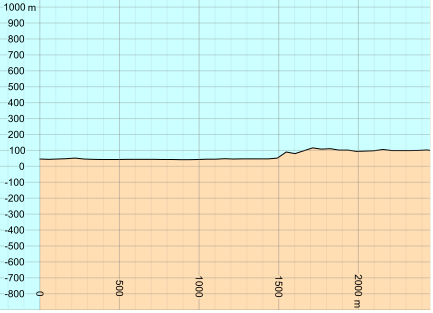
If you use the default View.AreaMode, which is AdjustToDrawable, your vertical profile view will usually show more than the specified View.Area, to ensure that the vertical scale is the same as the horizontal scale. This is realistic but not so exciting.
 |
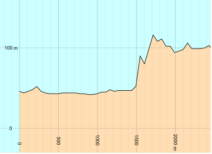
It is usually better to use View.AreaMode = Exact instead, since this lets you implement a vertical zoom that is independent from the horizontal zoom. In the image below, the view has displayed exactly the specified View.Area.
 |
The exact area mode also allows you to implement a zoom-to-extent button (which will adjust the vertical and horizontal zoom to show everything there is to see). You implement the zoom-to-extent button by calling the VerticalProfileOperator.GetFeatures, and then, for each output feature except polygons with the attribute vpopSourceGeoType #routeLine, you call Feature.CalculateBounds and insert the bounding rectangle into a RectangleSet, and finally you use the RectangleSet.Bounds as your View.Area.
Inheritance Hierarchy
System.Object
EngineObject
Operator
VerticalProfileOperator
Platforms
Windows, Linux, Android
VerticalProfileOperator Members
The VerticalProfileOperator type has the following members.
Constructors
| Name | Description |
|---|---|
| VerticalProfileOperator | Initializes a new instance of the VerticalProfileOperator class. |
Properties
| Name | Description |
|---|---|
| BottomElevation | Gets or sets the elevation, above sea level, at the lower vertical limit of each vector feature from ElevationInput. |
| Close | Gets or sets a flag that allows different output colors above and below ground. |
| ClosingHeight | Gets or sets the height at which lines are closed to polygons. |
| Description | Gets or sets a short description of the operator. Inherited from Operator |
| DisplayName | Gets or sets a display name for the operator. Inherited from Operator |
| ElevationInput | Gets or sets the input operator that gives elevation rasters or 3D vector data. |
| ElevationUnit | Gets or sets the vertical length unit of input features. |
| IsDisposed | Gets a value that tells whether the current VerticalProfileOperator has been disposed. Inherited from EngineObject |
| IsoMetadataDocument | Gets or sets the path to an ISO 19139 metadata document for the operator. Inherited from Operator |
| LandCoverHeightDefault | Gets or sets the default land-cover height that is used wherever LandCoverHeightInput does not give well-defined heights. |
| LandCoverHeightInput | Gets or sets the input operator that gives rasters containing the heights above ground of the land cover. |
| LandCoverInput | Gets or sets the input operator that gives land-cover rasters. |
| MaxDistance | Gets or sets the maximal distance from the route, at which 3D input can generate output. |
| Name | Gets or sets the name of the operator. Inherited from Operator |
| NativeHandle | Gets the native Carmenta Engine kernel object the current VerticalProfileOperator represents. Inherited from EngineObject |
| OutputRoute | Gets or sets a flag, telling whether the route shall be represented in the output. |
| RouteInput | Gets or sets the operator that gives the route line. |
| TopElevation | Gets or sets the elevation, above sea level, at the upper vertical limit of each vector feature from ElevationInput. |
| IUserProperties.UserProperties | Gets the AttributeSet that contains the user properties. Inherited from IUserProperties |
Methods
| Name | Description |
|---|---|
| Clone | Creates a copy of an object. Inherited from EngineObject |
| Dispose | Releases the reference to the native Carmenta Engine kernel instance the EngineObject represents. Inherited from EngineObject |
| Equals | Determines whether this instance is equal to another. Inherited from EngineObject |
| FindChildObject | Overloaded. Finds the child object with the specified name. Inherited from Operator |
| FlushCache | Removes the objects that have been cached by the operator. Inherited from Operator |
| GetChildObjects | Overloaded. Gets the child objects of the current object. Inherited from Operator |
| GetFeatures | Overloaded. Gets features from the operator chain. Inherited from Operator |
| GetLocalizedDescription | Gets a localized version of the operator description in a specific language. Inherited from Operator |
| GetLocalizedDisplayName | Gets a localized version of the operator display name in a specific language. Inherited from Operator |
| GetLocalizedIsoMetadataDocument | Gets the path to an ISO 19139 metadata document for a specific language. Inherited from Operator |
| GetRasterFeature | Overloaded. Gets raster features from the operator chain and merges them into a single raster. Inherited from Operator |
| HasLocalizedDescription | Checks if a localized version of the operator description is available in a specific language. Inherited from Operator |
| HasLocalizedDisplayName | Checks if a localized version of the operator display name is available in a specific language. Inherited from Operator |
| HasLocalizedIsoMetadataDocument | Checks if an ISO 19139 metadata document is available for a specific language. Inherited from Operator |
| ProjectToRouteCrs | Projects a feature from the vertical profile to the Crs of the line feature retrieved from RouteInput. |
| SetLocalizedDescription | Sets a operator description in a specific language. Inherited from Operator |
| SetLocalizedDisplayName | Sets a operator display name in a specific language. Inherited from Operator |
| SetLocalizedIsoMetadataDocument | Sets the path to an ISO 19139 metadata document for the operator, for a specific language. Inherited from Operator |