Projected Coordinates
Contents
Introduction
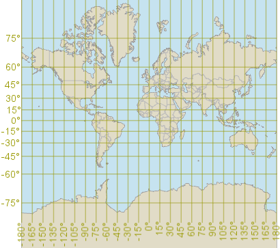
For many purposes, it is much easier to use a meter-based 2D Cartesian coordinate system instead of latitude and longitude. But you cannot wrap a graph paper around a whole terrestrial globe without tearing, wrinkling or stretching the paper. To make a flat map, one has to use a map projection like the Mercator projection, which is just a mathematical way to stretch the graph paper around the globe. (Tearing the paper is sometimes allowed, as in Goode's homolosine projection, but wrinkles are bad.)
 |
For a general introduction to map projections, we recommend Carlos A. Furuti's site Cartographical Map Projections. The text below concentrates on how projected coordinates (Easting and Northing) are used, with special emphasis on UTM and MGRS notation.
If you make a world map, you can cover it by a square grid. But you will usually find that the squares, although they are of equal size on the flat map, does not cover the same amount of true area on the round Earth. You can work around this by using a special kind of map projection, an equal-area projection, but then you will find that the region covered by a map square does not always look like a square on the round Earth: it may look like a rectangle or a skew parallelogram instead. So an accurate global square grid is not possible.
National Grids
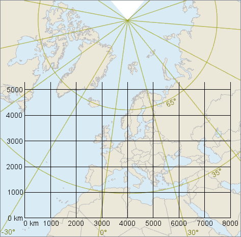
The good news that a square grid works approximately, if we can limit the area of interest to a small part of the Earth. For maps of Europe, for example, there is a recommended grid known as ETRS-LCC, based on a Lambert Conformal Conic projection. but the size of Europe still causes scale variations up to nearly 5 percent. To be precise, one true meter on the ground can be in the range 0.965 to 1.044 meters according to the grid (if between the parallels 29°N and 71°N).
 |
To get smaller scale errors, most small countries use their own map projection to make a national square grid. In Sweden, for example, the Land Survey recommends the SWEREF99 TM grid. The geodetic datum is SWEREF99, which coincides with WGS84 except for the continental drift since 1989 (about 0.8 meters as of 2021). The "TM" stands for the map projection, which is a Transverse Mercator. The grid looks like this:
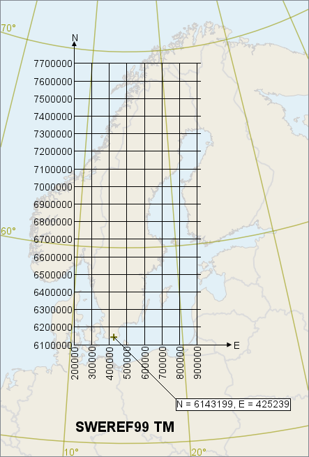 |
The coordinates of this grid are called N and E, and N should be given before E. (In general, the coordinate order of a national grid depends on national convention; see Axis order and axis names.) Between the meridians 12°E through Gothenburg and 18°E through Stockholm, the SWEREF99 TM grid coincides with the WGS84 UTM zone 33N grid (except for the 0.8 meter difference between SWEREF99 and WGS84). But note that E comes before N in UTM notation.
We mentioned above that the scale variation for the pan-European grid ETRS-LCC was nearly 5 percent. In SWEREF99 TM, the scale variation is less than 0.2 percent thanks to the smaller area. One true meter is between 0.9996 meters (at 15°E) and 1.0017 meters (in Haparanda) according to the SWEREF99 TM grid.
For applications that need higher accuracy, one can use a local grid with even smaller coverage. For example, the Swedish Land Survey recommends twelve local grids with names like SWEREF99 12 00 and SWEREF99 13 30, where the last two numbers give the central meridian (12°00'E and 13°30'E etc.).
See also Calculating with coordinates.
Grid North and True North
In a meter-based square grid, grid north often differs from true north. The difference is known as the meridian convergence, and can be quite noticeable.
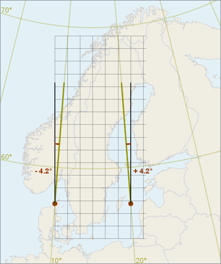 |
The meridian convergence at a given point should be possible to use as a constant offset between any grid bearing and the corresponding true bearing from that point. In other words, the difference between grid north and true north should be the same as the difference between grid southeast and true southeast, for example. (Actually, this works only if the grid is based on an angle-preserving (conformal) map projection, but that is usually the case for national grids.)
See also Calculating with coordinates.
Length Units
Most modern grids use the meter as length unit. However, state grids in the United States often use the foot, and it is usually the US Survey Foot which is slightly longer than the International foot. See LengthUnit.
The UTM Grids
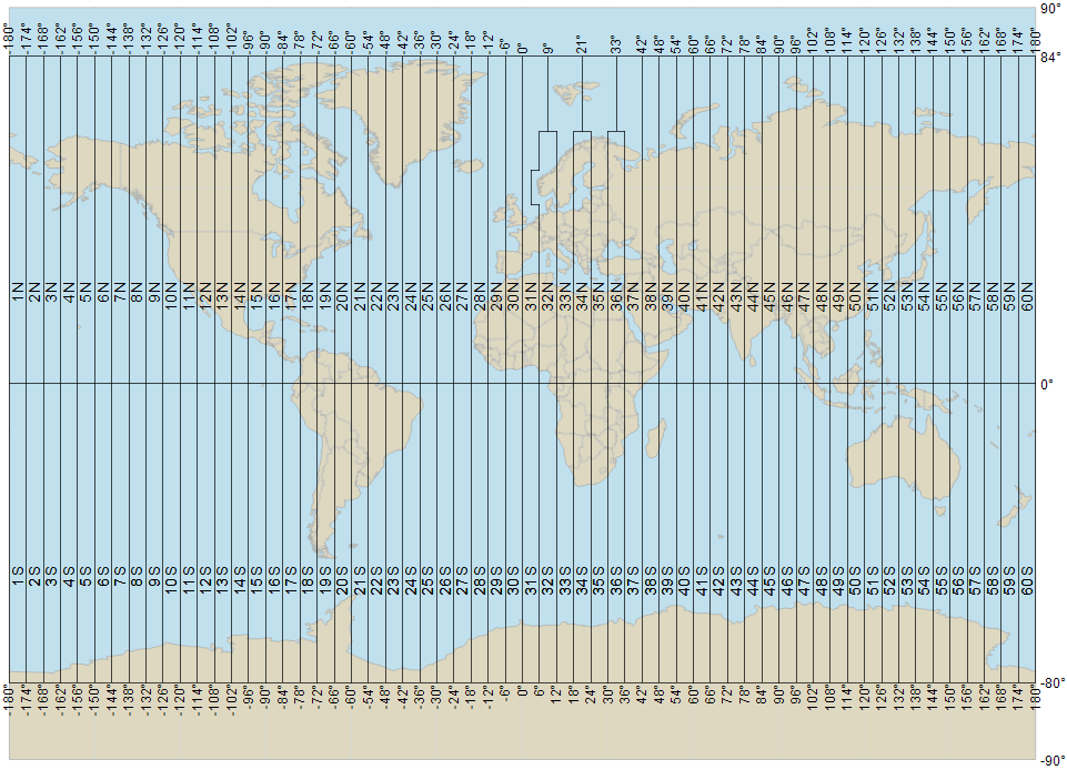
Instead of using national grids, which can be hard to keep track of, it can be simpler to use a set of 60 standardized grids, known as the UTM grids (Universal Transverse Mercator). Each UTM grid is used in its own zone that is a long narrow strip, 6 degrees wide. Since each zone is so narrow, it is possible to lay out a square grid for it with only small distortions.
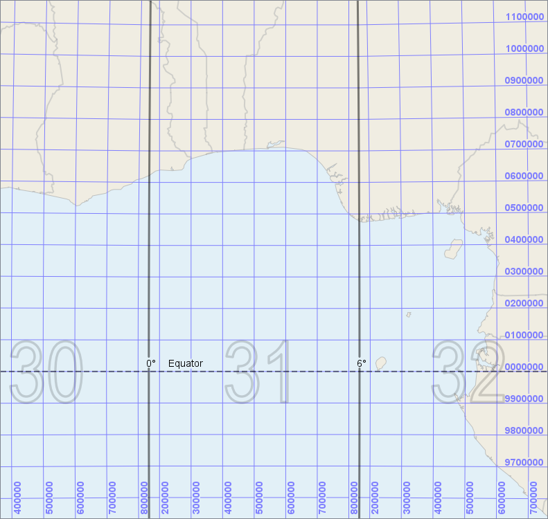
The coordinates in each UTM grid are called E and N, where E should be given before N. The E coordinate goes from about 166 000 to 834 000 meters east, arranged so that the line E = 500 000 m is the central meridian (the center of the zone). The N coordinate starts from zero near the south pole so that they reach 10 000 000 meters at the equator, but then N restarts from zero at the equator and goes towards 10 000 000 meters near the north pole. So N = 6 666 666 m can be either about 30° south of the equator, or about 60° north of the equator, and it is important to say whether you use the south or the north half of your UTM zone. The two halves are sometimes regarded as a single zone, sometimes as two separate zones.
The global numbering of the zones is given here:
 |
and the E and N coordinates near the equator are shown here:
 |
UTM applications
The UTM grids are nearly axis-parallel with each other near the equator, and the horizontal grid lines seem to cross the zone boundaries, but it is important to realize that the grids of different zones are incompatible. If you want to compute the distance from New York to London, the UTM grids are useless since the cities are in different zones.
Another problem is that if you want to compute distances inside a zone with high accuracy, better than about 0.10 percent, then the UTM grids are also useless, since distances according to the UTM grid are slightly wrong due to scale variation from the map projection. To get higher accuracy, one would need to use narrower zones.
So the UTM grids are useful for single-zone operations where you can accept a scale error up to 0.10 or 0.15 percent. To handle an operation across a zone boundary, you can extend the UTM grid of one zone into a neighboring zone, but not too far: the extended UTM grid should usually not go farther than 400 km from its central meridian.
A typical application of UTM is in artillery operations.
Finding UTM coordinates
We have seen the UTM grids near the equator, in a small scale. Let us now zoom in more, in south Scandinavia:
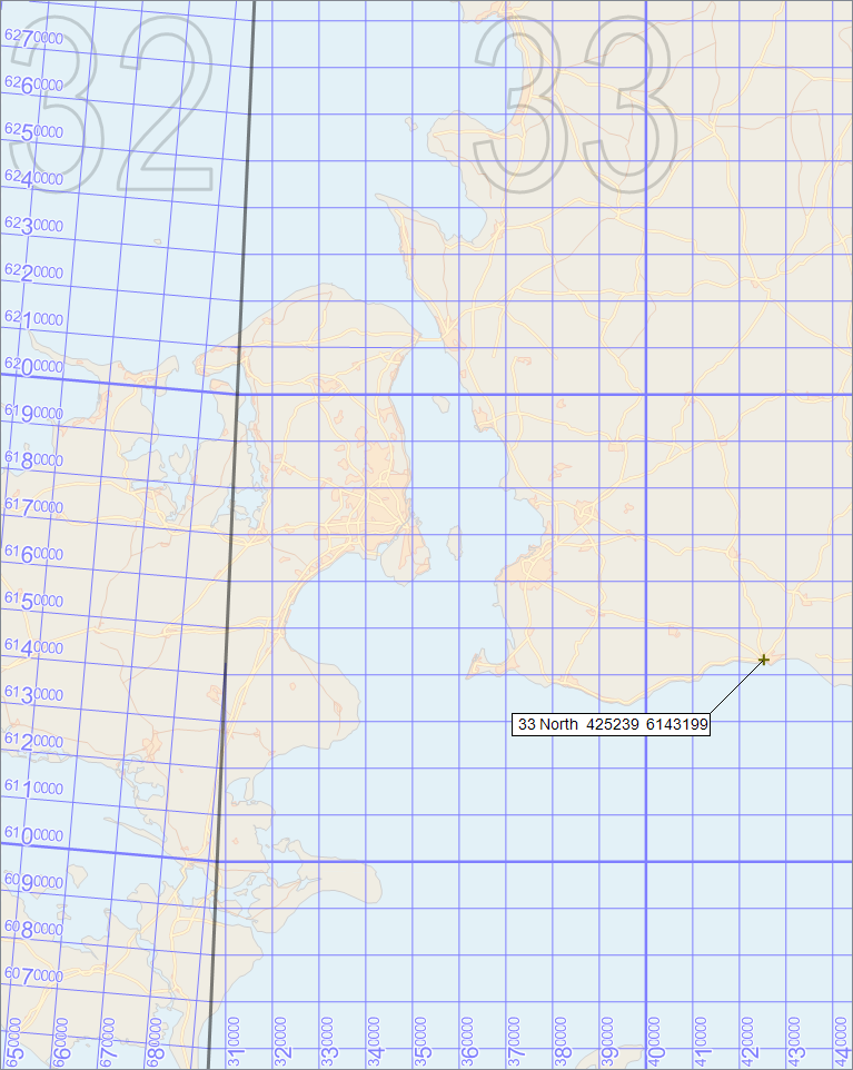 |
At these latitudes, it is more clear that the UTM grids of zone 32 and 33 are not axis-parallel, since each grid is axis-parallel to its own central meridian, and when we are this far from the equator, the central meridians of zone 32 (at 9°E) and zone 33 (at 15°E) have begun to approach each other so they are no longer locally parallel (although they would appear parallel in a cylindrical map projection like Mercator). You can also see that each UTM zone gets more narrow towards the poles (more narrow when measured in meters, that is: each zone is still 6 degrees wide, but the meridians converge toward the poles).
The grid line spacing is now 10 km, which means that in the grid labels, only the fifth digit from the right changes at each grid line. In the map, we have emphasized the changing digit by making it larger; this is a common convention, and the large digit is called a principal digit. In a printed map, the trailing zeros are often omitted for most of the grid labels, and the leading digits may also be omitted except at the grid lines where they change.
If we had zoomed in so much that we needed a grid line spacing of 1 km, then the UTM grid should show two principal digits for each grid label, and only three trailing zeros. We will see an example of this later, in the section about the alphanumeric MGRS notation for UTM.
There is no unique standard for the UTM syntax, but our example position in Ystad can be expressed in UTM as
33 North 425239 6143199
or as
425239, 6143199, zone 33 North.
This notation uses North or South to tell which half of the zone that is intended, which is important since the northing coordinates restart from zero at the equator. People sometimes write just N or S for the hemispheres, but this can be mistaken for a different notation, where a latitude band letter in the range C to X (excluding I and O) is used to denote a certain latitude interval. The official recommendation from NGA is that UTM notation should use the latitude band letter, and if the hemisphere is given anyway, then the hemisphere abbreviations N and S are not permitted; see the section Mixing UTM and MGRS Notation for more details.
Finally, the UTM grids must technically be based on a geodetic datum. Nowadays, they are usually based on WGS84, but they have previously been based on various national or continental geodetic datums. (Not the old Swedish RT90 datum, though: older Swedish maps show UTM grids based on ED50, the European Datum 1950.)
If you just have UTM coordinates, you must also find out whether the UTM grids are based on WGS84 or something else, otherwise you can be mistaken by hundreds of meters.
See also the Coordinates section in the Carmenta Engine FAQ.
MGRS: An Alphanumeric Way to Write UTM Coordinates
The Military Grid Reference System, MGRS, is an alphanumeric and hierarchic way to express UTM coordinates.
A full MGRS reference consists of three parts:
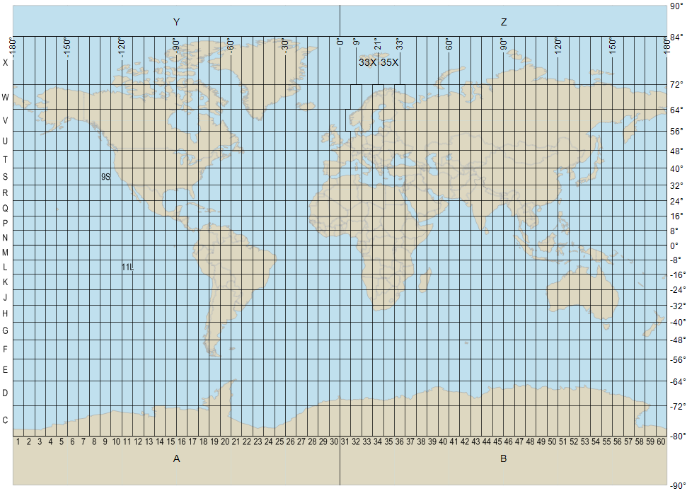
A grid zone designation, like 33U, that stands for a grid zone: a 6° by 8° long/lat rectangle.
A 100 km square identifier, like VB, that stands for a 100 km square within the grid zone.
A numeric location, like 25239 43199, that gives local easting and northing coordinates within the 100 km square, counting from the southwest corner.
The first part, or the first two parts, may be omitted if they are clear from context (although the context can be hard to understand for computer systems).
Also, if you do not need 1 meter resolution, you can drop digits from the right in the local easting and northing, so that you get 10 meter, 100 meter, 1 km or 10 km resolution.
Strictly speaking, there should be no spaces or other separators in an MGRS reference, but people often use spaces between the three parts, and also between the local easting and northing. We will do so in our examples.
Let us look at the details of each part.
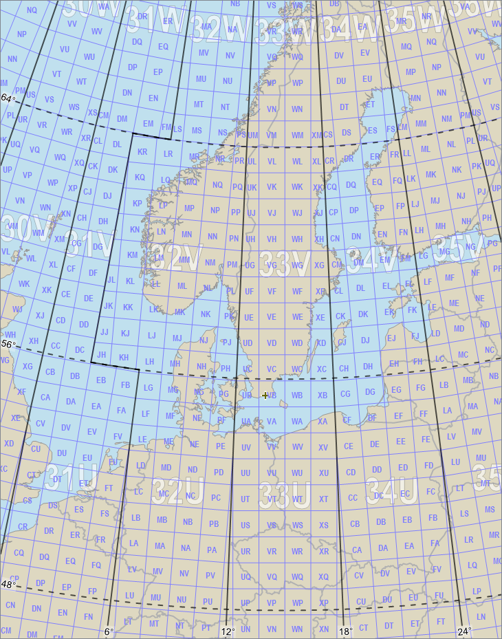
The grid zone designation consists of a UTM zone number (1 to 60) followed by an uppercase latitude band letter (C to X, omitting I and O) that stands for an 8-degree latitude band (although the northmost band is 12 degrees).
 |
The 100 km square identifier consists of two uppercase letters, a column letter followed by a row letter.
The column letters go from A to Z (omitting I and O) eastward through three adjacent zones before they start over from A. Some column letters are not needed far from the equator where the UTM zones are narrower (but these column letters can be used if you need to extend a UTM grid beyond its standard zone).
The row letters go from A to V (omitting I and O) northward and then start over from A (in a different latitude band). However, there is a different row letter offset for even and odd UTM zones.
 |
The numeric location consists of a local easting followed by a local northing within a 100 km square. The number of digits depends on the resolution you want.
If you want 1 meter resolution, the local easting is given in meters from the west edge of the square, and the local northing is given in meters from the south edge. This means that the numerical location gets 5 + 5 digits.
If you want 10 meter resolution, drop the last digit of the local easting and northing, which gives 4 + 4 digits for the numerical location.
If you want 100 meter resolution, drop the last two digits, which gives 3 + 3 digits.
If you want 1 km resolution, drop the last three digits, which gives 2 + 2 digits.
If you want 10 km resolution, drop the last four digits, which gives 1 + 1 digits.
If you want 100 km resolution, omit the numeric location completely.
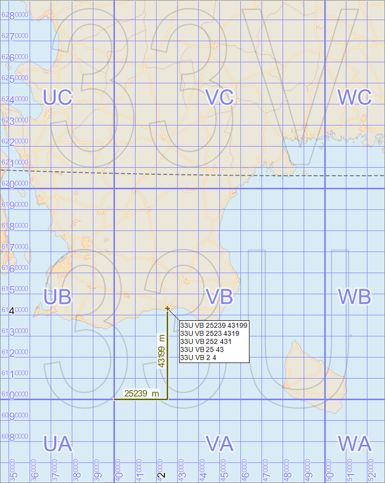 |
In the image above, we have 10 km grid line spacing, which means that the local easting starts with the principal digit of the vertical line that is just left of our position. This is the black 2 at the bottom of the image. Likewise, the local northing starts with the principal digit of the horizontal line that is just south of the position; this is the black 4 to the left in the image. The remaining digits of the local easting and northing must be measured by protractor in the map, or by some other means (obviously, you cannot get 1 meter resolution by measuring in a map of this scale).
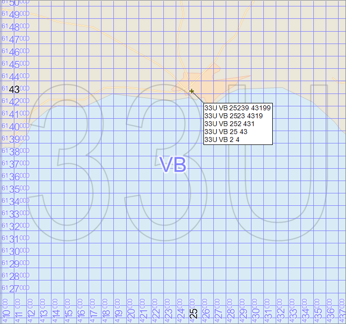 |
In the image above, we have zoomed in so much that the grid line spacing is 1 km, which means that there are two principal digits in each grid line label, not just one. So the local easting starts with the two principal digits (25) of the label for the vertical line just to the left of our position. And the local easting starts with the two principal digits (43) of the horizontal line that is just south of our position.
We can note that the leading superscripted digits in the grid labels, 4 at the lower edge and 61 at the left edge, are not used in the MGRS reference. The information these digits provide in pure UTM notation is instead provided by the grid zone designation and the 100 km square identifier in the MGRS notation. So, one might say that the two last images gave a hybrid map annotation that can be used to find both pure UTM coordinates and pure MGRS references.
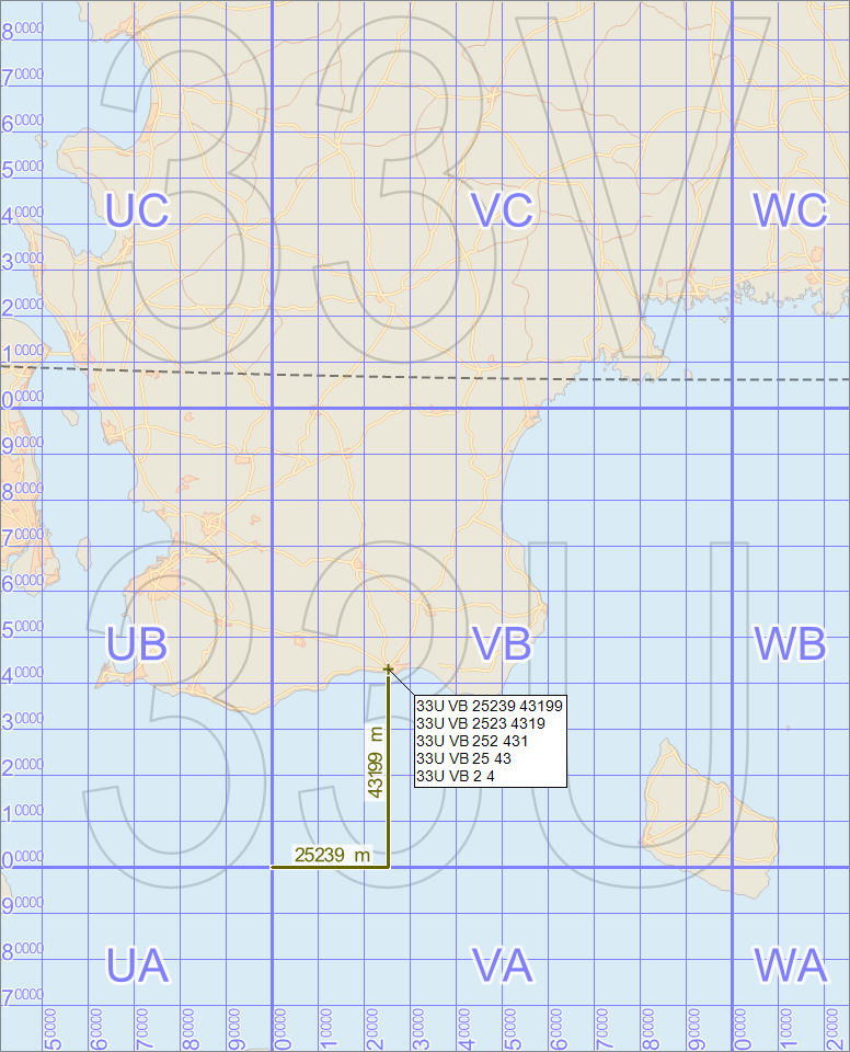
This hybrid annotation is of course useful on printed maps, but it may cause confusion since it has redundant information. In computer maps, it can be possible to choose between either pure UTM annotation or pure MGRS annotation. In the pure MGRS annotation, the leading superscripted digits would be omitted from the grid labels since they are not used in MGRS. So, such a map could look like this:
 |
Old and new MGRS
There are, in fact, two versions of the MGRS lettering scheme for the 100 km squares. In the examples above, we have shown the new scheme that is used for WGS84. The old scheme has row letters shifted 10 steps, and is used only for a few old geodetic datums; the most important is NAD27 (North American Datum 1927). However, there is a civilian version of MGRS used on US territories, USNG, which uses the new lettering scheme regardless of geodetic datum.
Usually, an MGRS reference that is valid in one lettering scheme is invalid in the other one (a 100 km square of the given name will not exist in the given grid zone), so software can warn when the wrong scheme is used. Unfortunately, some software will search further north until it finds the 100 km square in the next grid zone, and does not notice the error. If usage of the wrong lettering scheme is not detected, there will be a position error of 1000 km.
Mixing UTM and MGRS Notation
We have seen that our position in Ystad can be written in UTM as
33 North 425239 6143199
The "North" in the UTM syntax gives the hemisphere of the UTM zone (North or South).
In MGRS, the same position is written
33U VB 25239 43199
where the U stands for the latitude band between 48° and 56° North.
However, a common practice is to use UTM syntax, but replacing the hemisphere name by a latitude band letter from MGRS, which gives a MGRS-UTM hybrid notation:
33U 425239 6143199
When the hemisphere names are written in full as "North" or "South", the UTM notation with hemispheres cannot be confused with the hybrid notation. Unfortunately, it is not uncommon to use N and S and abbreviations for the hemisphere names, which makes it ambiguous whether N and S represent hemispheres or latitude bands.
The UTM and MGRS systems date from the late 1940s, but an official recommendation about this ambiguity was not available until 2014, when the US National Geospatial-Intelligence Agency (NGA) published revised versions of the basic UTM and MGRS documents, reference 3 and 4 in the paragraph "Other Resources" below.
Reference 3 forbids the use of "N" and "S" as hemisphere abbreviations and recommends only the hybrid notation for displaying UTM coordinates; Appendix A says:
A-4. Other applications such as coordinate readouts in Geographic Information Systems
(GIS) or coordinate conversion software also may require the display of full UTM/UPS easting
and northing values. In such cases, UTM/UPS coordinates are preceded by the grid zone
designator. Examples for UTM and UPS, respectively:
15F, 486911, 3852087
Y, 1735147, 2243078
A-5. When referencing full UTM coordinates, the hemisphere must NOT be designated
with a capital "S" or "N" immediately after the UTM zone, e.g. "15S". The danger of doing
so is that the "S" may be interpreted as the MGRS latitudinal band from 32°N to 40°N.
Instead, the MGRS latitudinal band identifies the hemisphere.
Reference 4, on the other hand, says that UTM zone numbers are signed, being positive for zones on the north hemisphere and negative for zones on the south hemisphere. Section 12.11 approves the MGRS-UTM hybrid notation, but also says:
Also for readability, UTM may show "31 north" in place of "+31", but the capital
letters "N" and "S" may not be used as abbreviations for north and south.
Reference 3 uses only unsigned numbers for UTM zones, and it seems that a + or - for the hemisphere is rarely used in coordinate presentations for human operators, although it is used internally in some metadata formats for military datasets.
Map Styles for UTM and MGRS Annotations
The UTM/MGRS grids and their annotations are usually blue on civilian aeronautical maps, but often black on military maps. If a military map includes a part of a UTM zone boundary, the map can use black grid lines on one side of the boundary and blue grid lines on the other side.
On printed maps, the grid zone designations (like 33U and 33V) are not as large as in our examples; they can instead appear in small print in the map margin, or on either side of the grid zone boundaries. The 100 km square identifiers (like UB and VB) are often written in every corner of their square, instead of once in the center as we have done. In a large-scale (zoomed in) map, every 100 km square will be interrupted by the map edges, so it is enough to write the square identifiers in the margin.
There is another alphanumeric scheme that is based directly on latitude/longitude, the GEOREF system that is somewhat out of fashion. We mention it because it uses uppercase two-letter names for 15-degree squares and also for 1-degree squares, so if a map shows annotations for both MGRS and GEOREF, it is easy to confuse the MGRS 100 km square names with the GEOREF 1-degree square names. You are supposed to distinguish them by color: UTM/MGRS names are usually blue or black, while GEOREF names are usually brown or red-brown.
Previous: Geographic Coordinates: Latitude and Longitude
Up: Coordinate Systems: Contents
Next: Classes for Coordinate Reference Systems
Reference
Projection
GridGenerator
UtmGridGenerator
GeorefGridGenerator
Crs.ParseMgrs
Crs.FormatMgrs
Crs.FormatUtmUps
Other Resources
Universal Grids and Grid Reference Systems, version 2.0.0. NGA Standardization Document, Office of Geomatics, 2014.
The Universal Grids and the Transverse Mercator and Polar Stereographic Map Projections, version 2.0.0. NGA Standardization Document, Office of Geomatics, 2014.