UtmGridGenerator Class
Generates a UTM or MGRS grid.
NuGet/Assembly: Carmenta.Engine.5.17.2.nupkg (in the CEOperators assembly)
Syntax
public class UtmGridGenerator : GeneratorRemarks
There is a map configuration sample grid.px that demonstrates how to configure a UtmGridGenerator to produce different kinds of geographical grids.
This generator is used to create the UTM grid system.
 |
 |
 |
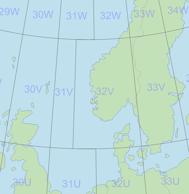
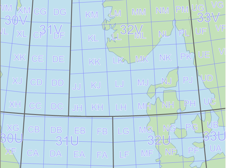
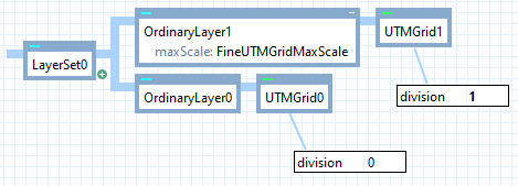
An instance of UtmGridGenerator can create either the coarse part or the fine part of the UTM grid, with annotations in MGRS style (named rectangles with annotated grid lines) or in plain UTM style (numbered zones with annotated grid lines). You will get the coarse part of the grid if Division is 0, and the fine part if it is 1. To display a complete UTM grid, you need to use two instances of the generator, one for each division. Each instance can be placed in its own layer, and the layer showing the fine grid (division 1) should have a maxScale of about 5 million.
 |
There is an MGRS grid example in the grid.px configuration file in the Carmenta Engine samples/MapConfigurations folder. For an introduction to UTM and MGRS coordinates, see the Style property and the Projected Coordinates article.
The alphanumeric system MGRS gives names to squares and rectangles of the UTM grid, so these names appear as string attributes of generated features. A name-carrying feature can be either a point feature in the center or the southwest corner of the rectangle, or a polygon feature that covers the rectangle. The default is to use point features, but at zoomed-in scales it is important to use polygons instead. See NameCarrier for details.
You can also choose whether the MGRS name for a square or rectangle should appear in the center or in the southwest corner, see NamePlacement.
The UTM grid generator creates visualizers as well as features, so if you like the default visualization, there is nothing more you need to do. But you can control the created visualizers via the properties Font, LineColor, LineWidth, TextColor, TextHaloColor and TextHaloWidth.
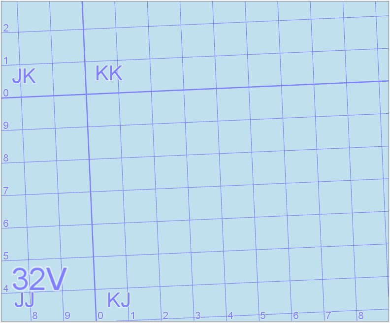
The built-in visualization for line labels depends on the Style. If the style is UTM, there will appear complete UTM coordinates (6 digits for vertical lines and 7 digits for horizontal lines). In the MGRS styles, the line label will be larger and just show the principal digits: the digits that are important for finding an MGRS reference in the current scale. The first of the principal digits is always the 10000-meter digit of the complete UTM coordinates (the fifth digit counting from the end). To decide how many principal digits there should be, the UTM grid generator follows the military MGRS convention recommended by NGA (US National Geospatial-Intelligence Agency). It is unfortunate that the civilian variant of MGRS, the United States National Grid (USNG), uses a different convention.
Line distance in grid | Number of principal digits (MGRS) | Number of principal digits (USNG) |
|---|---|---|
10 000 m | 1 | 2 |
1 000 m | 2 | 2 |
100 m | 3 | 2 |
10 m | 4 | 2 |
1 m | 5 | 2 |
On a printed map with an MGRS or USNG grid, you can find at least some lines where the principal digits are preceded and followed by small superscript numbers, so that one can read the complete UTM coordinate of the line. This mixed-size line label style is not supported by the built-in visualizer, but you can implement it manually, by using some attributes of the lines from the generator. A listing of the feature attributes from the generator appears below.
However, that listing and the rest of these remarks can be skipped by most users, who can just rely on the built-in visualizers.
Literature
The reference documents have been published by NGA, the US National Geospatial-Intelligence Agency. Reference 1 is the basic one, with a wide scope. Reference 2 is shorter and easier to read. Reference 3 is intended for GIS software developers, and also gives details about some subtle issues about MGRS notation.
Universal Grids and Grid Reference Systems, version 2.0.0. NGA Standardization Document, Office of Geomatics, 2014.
The Universal Grids and the Transverse Mercator and Polar Stereographic Map Projections, version 2.0.0. NGA Standardization Document, Implementation Practice. Office of Geomatics, 2014.
See also the Wikipedia articles on UTM and MGRS.
Six combinations
The two possible divisions (0 and 1) and the three possible styles (NewMgrs, OldMgrs, and Utm) can be combined in six ways, described below.
Style | division = 0 (coarse grid) | division = 1 (fine grid) |
|---|---|---|
NewMgrs | The vertical grid lines will be the boundaries the UTM zones, normally a meridian for every 6th degree; their value attribute contains their longitude. The horizontal grid lines will be latitude circles, normally every 8th degree; their value attribute contains their latitude. Each 6° by 8° rectangle (a grid zone) has a name, consisting of the zone number and a letter for the latitude band. The polar caps are divided in halves that have one-letter names. The names are the value attributes of features, either polygons or points, depending on NameCarrier. | Within each zone, a grid is drawn for the UTM projection in the zone. Each 100-km square gets its two-letter MGRS name, in the new version of MGRS (the northing letter of squares just north of the equator is A in odd zones and F in even zones). With MGRS, the built-in visualizer for line labels will show only the principal digits, which are stored in the mgrsPrincipal attribute of the line, which is described further down. |
OldMgrs | Same as NewMgrs. | Same as NewMgrs, except that the old version of the naming scheme is used. The northing letter of 100-km squares is shifted ten steps in the alphabet, so that the northing letter of squares just north of the equator is L in odd zones and R in even zones. (To learn why there are two versions of MGRS, see GeodeticDatum.) |
Utm | The grid shows only the boundaries between the UTM projection zones: usually every 6th meridian, and the latitude circles at 80°S and 84°N, and the equator (where the UTM northing restarts from zero). The zone number will appear as the value attribute of a feature, either a line with lineType = 2 or a polygon, depending on NameCarrier. | Same as NewMgrs or OldMgrs, except that the names of the 100-km squares are not generated, and the built-in line label visualizer will show the utmComplete attribute of the line. |
Line attributes
Regardless of Division, the generated lines will have the following attributes.
Attribute | Type | Possible values |
|---|---|---|
lineType | System.Int64 | 0: a horizontal grid line; 1: an ordinary vertical grid line; 2: a vertical line that carries a zone number when Division is 0 (coarse grid) and the Style is Utm. (Do not visualize the line, only its value attribute.) |
value | System.Double or String (not available in C#) | The longitude or latitude for Division 0 (coarse grid), the easting or northing for Division 1 (fine grid), or the UTM zone number if the lineType attribute is 2. The value attribute may be absent, if the ValueAttributeFormat is None. In division 0, it can make some sense to use ValueAttributeFormat = StringDeg or StringDegPrefixed, but the built-in visualizers will not display the value attribute of lines, since longitude and latitude are not used in UTM or MGRS coordinates. You can display them with your own text visualizer if you like. In division 1, the value attribute of lines not should be used. The built-in line label visualizer will show either the utmComplete attribute or the mgrsPrincipal attribute, depending on Style. (You can also choose to display the usngPrincipal and usngNecessarySuffix attributes with your own visualizers instead, since USNG recommends a label style that differs from MGRS.) |
impactAngleAtStart | A System.Double, usually between 0° and 90° | The angle between the line start and the edge of the map, or -91° if the line starts in the interior of the map. |
impactAngleAtFinish | A System.Double, usually between 0° and 90° | The angle between the line end and the edge of the map, or -91° if the line ends in the interior of the map. |
If Division is 0, the lines will also have the following attribute:
Attribute | Type | Possible values |
|---|---|---|
isZoneBoundary | System.Boolean | True: the line is a boundary between projection zones, and will interrupt the 100-km squares of the fine grid; False: the line is a latitude circle or a polar-cap bisector that will not interrupt the 100-km squares. You can visualize the zone boundaries with thicker lines. (If the lineType attribute is 2, the isZoneBoundary attribute will not be defined.) |
If Division is 1, the lines will also have the following attributes:
Attribute | Type | Possible values |
|---|---|---|
lineAndProjType | Atom | #horizontalUTM: a horizontal line in a UTM zone; #verticalUTM: a vertical line in a UTM zone; #horizontalUPS: a horizontal line in UPS (north or south); #verticalUPS: a vertical line in UPS (north or south); |
greatestRoundDivisor | System.Int64 | 500 000, 200 000, 100 000, 50 000, 20 000, 10 000, ..., 5, 2, 1. It will be the greatest of these that is a divisor of the line coordinate. You should highlight lines whose greatestRoundDivisor is at least 100 000. |
startType | Atom | #interior, if the line starts inside the presentation borders; otherwise, #left, #right, #top or #bottom, depending on from which edge the line starts. (This attribute will not be useful under a TileLayer.) |
finishType | Atom | #interior, if the line finishes inside the presentation borders; otherwise, #left, #right, #top or #bottom, depending on at which edge the line finishes. (This attribute will not be useful under a TileLayer.) |
isShort | System.Boolean | if True, the line is so short that its label should not be shown, unless the line reaches a border of the presentation. (For example, the horizontal lines in the northwest corner of 32V.) |
bestEnd | Atom | #start: the generator recommends that you show the line label at the start of the line (use PointVisualizer.At = 0.0). #finish: the generator recommends that you show the line label at the finish of the line (use PointVisualizer.At = 1.0). #neither: the generator thinks that neither end is a good place for the label. |
marginWest | System.Int64 | For a UPS line or a horizontal UTM line: the maximal integer. For a vertical UTM line: the number of pixels from the best end of the line to the west boundary of the UTM zone. (If the line label is right-aligned, omit the label when marginWest is too small.) |
marginEast | System.Int64 | Like marginWest, but using the east boundary. |
utmComplete | String (not available in C#) | The complete UTM coordinate of the line: 6 digits for vertical lines and 7 digits for horizontal lines. |
valuePrefix | String (not available in C#) | The first one or two digits of the numerical value of the line (all digits except the five last). |
mgrsPrincipal | String (not available in C#) | When you want to label lines according to the military convention of NGA, use this string that contains the principal digits of the numerical value of the line. According to NGA, these start with the 5th digit from the end of the numerical value, and consists of 5 - z digits, where z is the number of zeros in the number that expresses the grid line distance. |
mgrsSuffix | String (not available in C#) | The remaining digits of the numerical value of the line, after the valuePrefix and the mgrsPrincipal have been removed. |
usngPrincipal | String (not available in C#) | When you want to label lines according to the civilian convention of United States National Grid (USNG), use this string that contains the principal digits of the numerical value of the line. According to USNG, these are always the 5th and the 4th digit from the end (the 10 000 and the 1 000 digits), regardless of the grid line spacing. |
usngCompleteSuffix | String (not available in C#) | The remaining digits of the numerical value of the line, after the valuePrefix and the usngPrincipal have been removed. This string will always contain 3 digits. |
usngNecessarySuffix | String (not available in C#) | The initial digits of the usngCompleteSuffix that are necessary to display for each grid line (usually in a smaller and superscripted font) after the usngPrincipal string. If the grid line spacing is 10 000 m or 1 000 m, this string will be empty. If the grid line spacing is 100 m, it will consist of the first digit of the usngCompleteSuffix. If the grid line spacing is 10 m, it will consist of the first two digits of the usngCompleteSuffix. If the grid line spacing is 1 m, it will consist of the all three digits of the usngCompleteSuffix. |
Rectangle attributes
The features that carries rectangle names (square names, zone numbers) will have the following attributes.
If Division is 0 (coarse grid):
Attribute | Type | Possible values |
|---|---|---|
value | String (not available in C#) | With an MGRS Style: a string that is the name of a 6° by 8° rectangle, containing a zone number and a letter for the latitude band, like 33V. With the plain UTM Style: a string that is the zone number, like 33. |
If Division is 1 (fine grid) and the Style is an MGRS style:
Attribute | Type | Possible values |
|---|---|---|
value | String (not available in C#) | A two-letter string that is the name of a 100-km square, like UD. |
eastingLetter | String (not available in C#) | The first letter of the square name, like U. |
northingLetter | String (not available in C#) | The second letter of the square name, like D. |
fullValue | String (not available in C#) | A string that is the name of the 6° by 8° rectangle followed by the name of the 100-km square, like 33VUD. |
width | System.Int64 | The width of the 100-km square, in pixels. You should use a Visualizer.Condition requiring that width is large enough to show the label (depending on font size etc). Note that 100-km squares are interrupted at the zone boundaries, so they can be quite narrow. |
height | System.Int64 | The height of the 100-km square, in pixels. You should use a Visualizer.Condition requiring that height is large enough to show the label (depending on font size etc). Note that 100-km squares are interrupted at the zone boundaries, so they can be quite low (although most zone boundaries are vertical lines). |
A 100-km square may cross a border between two latitude bands. The square will still appear as one square, provided you display the value attribute of squares.
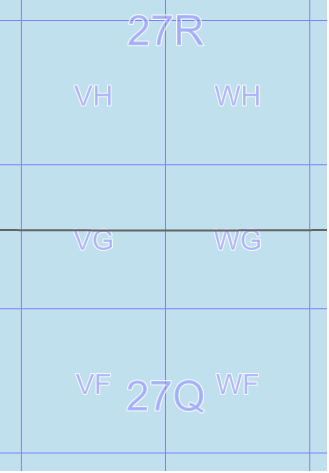 |
But the square will appear as two named parts if you display the fullValue attribute of squares, since the northern part and the southern part will have different letters for the latitude band.
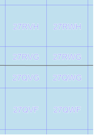 |
Actually, there is an exception to the above rule: if you just display the value attribute, and if the NamePlacement says that the 100-km square names shall be placed in the southwest corner of the square, then a square that crosses a latitude band boundary can get its name duplicated in the southwest corner of each part, if the scale is zoomed in enough (and there is room for the name).
If Division is 1 but Style is the plain Utm style, then no features that carry square names will appear in the output.
Requirements on visualizers
To handle all possibilities, the visualizers of your VisualizationOperator must satisfy certain requirements.
The LineVisualizer that draws the grid lines must have a Visualizer.Condition that the lineType attribute is 0 (horizontal) or 1 (vertical). Alternatively, you can have one line visualizer that requires that lineType = 0, and another one that requires that lineType = 1. In this way, the line visualizer avoids drawing the center line of a zone (with lineType = 2), or drawing a polygon feature (lacking a lineType attribute) that carries a rectangle name. (If Division is 1, you can check the lineAndProjType attribute instead, since polygons that carries the square names will lack that attribute.)
If Style is Utm and Division is 0, then you may need two text visualizers to show the zone numbers, which may be carried by either lines or polygons (depending on the NameCarrier). Let us assume you want to place the zone numbers at the bottom edge of the map. Then, if the zone numbers may be carried by lines, you need a text visualizer with a condition that the lineType = 2, and with at = 0 and repeat = No. But if the zone numbers may be carried by polygons, you need a text visualizer with a condition that the geoType attribute equals #polygon, and with at = 180° and repeat = FarthestAtDirection. If your NameCarrier property depends on the view scale, then your VisualizationOperator must be prepared for both lines and polygons that carry zone numbers, so it needs both these text visualizers.
Otherwise (Style is an MGRS style or Division is 1, or both), one text visualizer is enough to show rectangle names (square names). It must have a condition that the geoType attribute equals #point or #polygon. If the name carrier may be a polygon, you can use atCenter = True to get the name in the center, or you can use at = 225° and repeat = FarthestAtDirection to get the name in the lower left corner (these properties are harmless if the name carrier is a point).
For Division 1 with an MGRS style, and line distances less than 100 000 m, you will need to highlight the grid lines that form the borders between the 100-km squares, otherwise it is hard to see the extent of a named 100-km square. Use a highlighting line visualizer (thicker lines, say) with a condition that greatestRoundDivisor is at least 100000, and use a "lowlighting" line visualizer with a condition that greatestRoundDivisor is at most 50000.
Inheritance Hierarchy
System.Object
EngineObject
Operator
Generator
UtmGridGenerator
Platforms
Windows, Linux, Android
See Also
Reference
Operators Module
Projected Coordinates
GarsGridGenerator
GeorefGridGenerator
GridGenerator
Crs.ParseMgrs
Crs.TryParseMgrs
Crs.FormatMgrs
UtmGridGenerator Members
The UtmGridGenerator type has the following members.
Constructors
| Name | Description |
|---|---|
| UtmGridGenerator | Initializes a new instance of the UtmGridGenerator class. |
Properties
| Name | Description |
|---|---|
| Description | Gets or sets a short description of the operator. Inherited from Operator |
| DisplayName | Gets or sets a display name for the operator. Inherited from Operator |
| Division | Gets or sets a flag controlling whether a fine or a coarse grid is generated. |
| Font | Gets or sets the font used for the text labels. |
| GeodeticDatum | Gets or sets the GeodeticDatum used for the grid. |
| IsDisposed | Gets a value that tells whether the current UtmGridGenerator has been disposed. Inherited from EngineObject |
| IsoMetadataDocument | Gets or sets the path to an ISO 19139 metadata document for the operator. Inherited from Operator |
| LineColor | Gets or sets the line color. |
| LineDistanceX | Gets or sets the distance between vertical grid lines, when Division is 1. |
| LineDistanceY | Gets or sets the distance between horizontal grid lines, when Division is 1. |
| LineWidth | Gets or sets the line width. |
| Name | Gets or sets the name of the operator. Inherited from Operator |
| NameCarrier | Gets or sets a value that controls which kind of features will carry names. |
| NamePlacement | Gets or sets a value that controls where names will be placed. |
| NativeHandle | Gets the native Carmenta Engine kernel object the current UtmGridGenerator represents. Inherited from EngineObject |
| PointDistanceX | Gets or sets the distance between point in the horizontal lines. |
| PointDistanceY | Gets or sets the distance between point in the vertical lines. |
| Style | Gets or sets a value that controls the style of grid to generate. |
| TextColor | Gets or sets the text color. |
| TextHaloColor | Gets or sets the text halo color. |
| TextHaloWidth | Gets or sets the text halo width. |
| IUserProperties.UserProperties | Gets the AttributeSet that contains the user properties. Inherited from IUserProperties |
| ValueAttribute | Gets or sets name of the attribute that holds the labels of the grid lines. |
| ValueAttributeFormat | Gets or sets the format of the line label attribute. |
Methods
| Name | Description |
|---|---|
| Clone | Creates a copy of an object. Inherited from EngineObject |
| Dispose | Releases the reference to the native Carmenta Engine kernel instance the EngineObject represents. Inherited from EngineObject |
| Equals | Determines whether this instance is equal to another. Inherited from EngineObject |
| FindChildObject | Overloaded. Finds the child object with the specified name. Inherited from Operator |
| FlushCache | Removes the objects that have been cached by the operator. Inherited from Operator |
| GetChildObjects | Overloaded. Gets the child objects of the current object. Inherited from Operator |
| GetFeatures | Overloaded. Gets features from the operator chain. Inherited from Operator |
| GetLocalizedDescription | Gets a localized version of the operator description in a specific language. Inherited from Operator |
| GetLocalizedDisplayName | Gets a localized version of the operator display name in a specific language. Inherited from Operator |
| GetLocalizedIsoMetadataDocument | Gets the path to an ISO 19139 metadata document for a specific language. Inherited from Operator |
| GetRasterFeature | Overloaded. Gets raster features from the operator chain and merges them into a single raster. Inherited from Operator |
| HasLocalizedDescription | Checks if a localized version of the operator description is available in a specific language. Inherited from Operator |
| HasLocalizedDisplayName | Checks if a localized version of the operator display name is available in a specific language. Inherited from Operator |
| HasLocalizedIsoMetadataDocument | Checks if an ISO 19139 metadata document is available for a specific language. Inherited from Operator |
| SetLocalizedDescription | Sets a operator description in a specific language. Inherited from Operator |
| SetLocalizedDisplayName | Sets a operator display name in a specific language. Inherited from Operator |
| SetLocalizedIsoMetadataDocument | Sets the path to an ISO 19139 metadata document for the operator, for a specific language. Inherited from Operator |