Aircraft Routing Tutorial
This tutorial describes how the AirRouteOperator can generate safe and fast drone routes through a list of given waypoints while avoiding dangerous airspaces, with an emphasis on finding terrain that offers concealment from ground-based enemies.
Before starting this tutorial, we recommend that you read the general introduction in the article Aircraft Routing. And you can find more gritty details in the manual pages for AirRouteOperator and AircraftType.
As a basis for this tutorial, we use the air_route_operator.px sample configuration, but since it fairly complicated, we will not describe how you could write it yourself step-by-step. Instead, we take the configuration as a starting point, describe some things you can do in Carmenta Explorer, and suggest some possible modifications.
1 Introduction
You can start by opening the configuration in Carmenta Explorer.
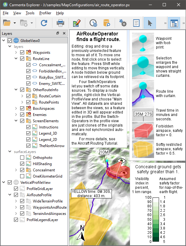 |
The instructions (upper left) and the two legends (right side) are worth studying. For the legend with the green color ramp, you do not need to understand the numeric labels right now; it is enough to note that the green colors do not indicate vegetation but places where the terrain offers some concealment, with darker green being more concealed. Then you can disable the instructions and the legends in the Layers panel, under ScreenElements.
As the instructions mentioned, you can explore the routing by editing the waypoints, the box airspaces and the big eyes that represent enemy observers. Some more advanced editing operations, like adding or removing nodes, are described under StandardTool.
2 Choosing a Resolution for the Routing Algorithm
The finest available elevation resolution in the Lake Tahoe samples geodata is 10 meters, but overview versions are also avaiable with resolutions of 20 m, 40 m, 80 m, etc. To improve the performance, the sample configuration computes in the 40 m resolution instead of 10 m, as controlled by the AirRouteOperator.DesiredResolution which in this configuration gets its value from the airRouteResolution attribute in the UpdateAttributeSet. A drawback is that if you use a lower value for the AirRouteOperator.VerticalClearance, the generated route may sometimes appear to go below ground. When Carmenta Engine generates overviews for raster datasets, it is possible to let the RasterCacheFilter be Max; this is the best setting for aviation and should have avoided most of the problem, but it was the Average setting that was used for the Lake Tahoe elevations. To compensate, the configuration uses a fairly high value for the vertical clearance. A low vertical clearance would benefit from calculations in the 10 m resolution, but the route could still appear to go below ground in rare cases; this is probably caused by the elevations being interpolated in different ways by the AirRouteOperator, the GlobeView and the VerticalProfileOperator.
3 Choosing a Cache Mode for the Ordinary Layer
In your own application, it would be best to use a dynamic OrdinaryLayer.CacheMode, preferably DynamicAsync, for all the ordinary layers that display results from the AirRouteOperator. However, as mentioned in the documentation of AirRouteOperator, the ID-giving input will then be the AirRouteOperator.WaypointsInput, so your application must detect modifications in the other input streams and then call the method MemoryDataSet.RefreshAllFeaturePresentation(false) for the ID-giving memory dataset that contains the waypoint features. Unfortunately, the general Carmenta Explorer application does not support this special behavior, so the sample configuration does not use a dynamic cache mode. However, there is a named object in the configuration, RouteLayerCacheMode, that is shared between the three relevant ordinary layers. If you use Carmenta Studio to change its Enumeration value from None to DynamicAsync, you can at least use Carmenta Explorer to get a feeling for the effects of the dynamic cache mode, since you can still edit the waypoints: you just have to refrain from editing the airspaces. (That is, you can edit the airspaces, but that would not cause the route to be updated until you also edit a waypoint or disable the three layers RouteLine, RouteCurtain and RoutePoints and enable them again.) The effects of the DynamicAsync cache mode will be more obvious if you also reset the value of airRouteResolution in the UpdateAttributeSet to 20 or 10 meters.
4 Handling Tree Heights
The sample configuration does not handle tree heights, but a treeHeightInput is available for the AirRouteOperator, the AirspaceCoverageOperator and the VisibilityIndexOperator, and analoguous properties landCoverHeightInput and landCoverInput for the VerticalProfileOperator, so sending tree heights to the operators is fairly easy. Examples can be found in other sample applications, like the line_of_sight_trees.px and the vertical_profile.px. But it can be a challenge to visualize forests well in 3D, so we ignore them in this sample. (One of the vertical profile operators in the sample does have a landCoverInput, but it is used to display concealment estimates instead of vegetation types.)
The configuration has a monochrome surface layer named Orthophoto that shows what the terrain looks like, but since it does not affect the analysis and makes it harder to see the Concealment surface layer, the Orthophoto is disabled at startup.
5 Toggling the Data Sources
You can learn much from editing the sample features, but this tutorial is focused on the effects of toggling the data sources. In the Layers panel, you can find the four SwitchOperators that were mentioned in the instructions:
ForbiddenBox_SWITCHOP
Enemy_SWITCHOP
RiskyBox_SWITCHOP
Concealment_SWITCHOP
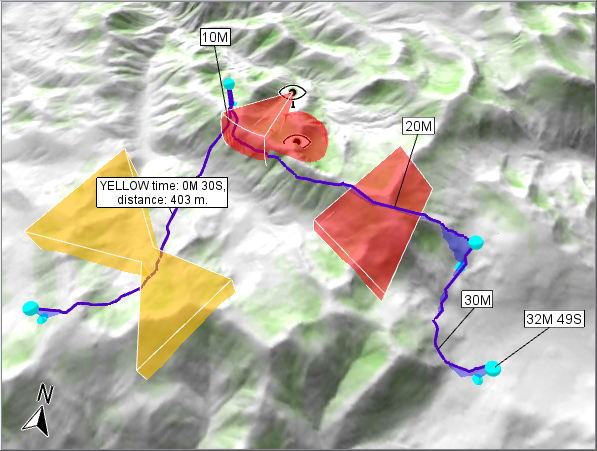
These can be used to toggle four data sources on and off, to see how they affect the routing. As a starting point, our next screenshot shows only the map window (without the legends), but all SwitchOperators are still enabled:
 |
A ScaleBar would not work in a GlobeView, but you can get a sense of distances by enabling the OneKilometerGrid surface layer, like this:
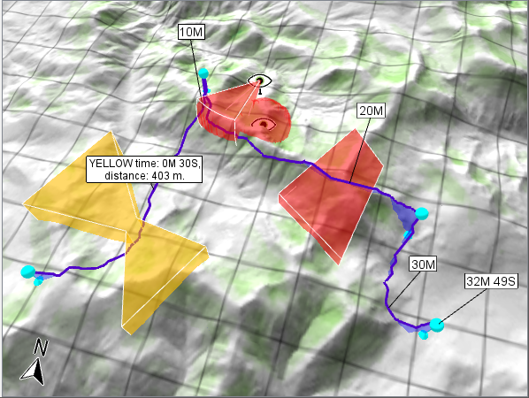 |
Note that both the grid layer and the Concealment layer have defined maxScale values. For performance reasons, this is essential in a GlobeView for surface layers that cannot give fast results when queried with coarse resolution over vast areas, although it means that the layers will not be displayed where the ground is too far from the GlobeView camera.
5.1 Using the vertical profile
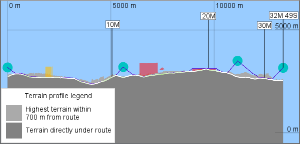
We can also see the results in the vertical profile along the route: just right-click on VerticalProfileView in the Layers panel and choose "Main View":
 |
Unfortunately, Carmenta Explorer cannot show the profile view and the globe view at the same time.
The profile in lighter gray displays the highest terrain within 700 meters from the route. Wherever that profile is higher than the flight route, it means that the terrain offers some concealment on at least one side of the route. The distance of 700 meters is somewhat arbitrary, but was chosen to be a little shorter than the one-kilometer sight range that is used to calculate concealment in a way that will be explained in section 6.
The four SwitchOperators can cause some confusion when using the vertical profile. If you study the configuration in Carmenta Studio, you will see exactly four instances of the SwitchOperator class. In the Layers panel in Carmenta Explorer, you can see their checkboxes many times, under each Layer that they affect, but checkboxes with the same name refer to the same instance of each SwitchOperator, as expected – but only within the same View! The checkboxes for the SwitchOperators that are visible in the VerticalProfileView refer to four clones of the originals, and Carmenta Explorer is not smart enough to keep their on/off-status automatically synchronized with their namesakes. Fortunately, the MemoryDataSets are truly shared between the two Views, so when you have edited a feature in 3D, you can then see the modification in the profile.
5.2 More about data toggling
Let us now return to the 3D View and explore the SwitchOperators. First, the ForbiddenBox_SWITCHOP refers to the red box-shaped airspace to the right. Its safety factor is defined by an airspace feature attribute, and since it is zero the airspace becomes forbidden, and indeed we can see that the generated route goes over it. If we disable this SwitchOperator, we get a different route:
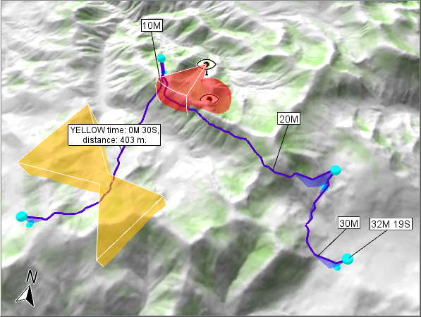 |
The Enemy_SWITCHOP controls the two enemy observers that are displayed as big eyes, and their combined viewshed. This viewshed is red because it is also forbidden, although it is not a box (extruded polygon) but represented by the special volume-encoding rasters that only a LineOfSightOperator or an AirspaceCoverageOperator can generate. The safety factor for the viewshed is defined in different way than for the red box. When the volume-encoding rasters are generated by an AirspaceCoverageOperator, as in the sample, we cannot attach the safety factor to the observer point features, since such an attribute would not survive the operator (in the general case, different observers could have conflicting attribute values that the operator cannot merge). Instead, the safety factor for the viewshed is defined by an AttributeOperator. The route manages to sneak under the viewshed thanks to a convenient ridge.
Our AirspaceCoverageOperator computes the union of the viewsheds, but since the union is completely forbidden due to its safety factor of zero, we could instead have used a LineOfSightOperator to generate two separate viewshed volumes. The AirspaceCoverageOperator is used here because it is more flexible: for example, if our aircraft is in danger only where it is seen by at least two observers simultaneously, we could handle that by increasing the value of AirspaceCoverageOperator.MinObservers from 1 to 2 in Carmenta Studio.
If we disable the Enemy_SWITCHOP, too, we find that the route now follows the other side of the ridge:
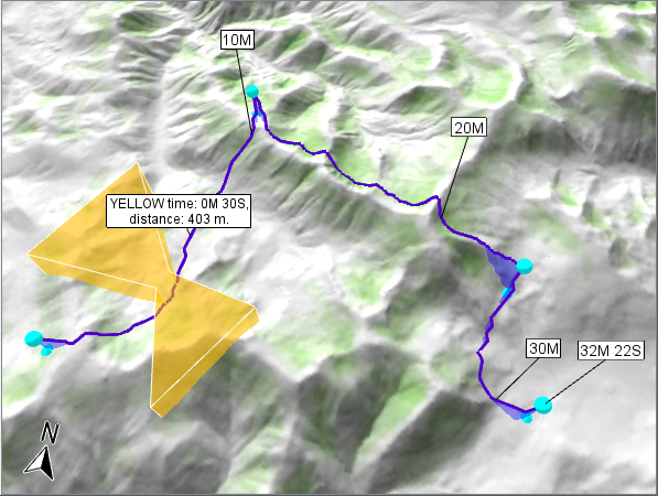 |
The RiskyBox_SWITCHOP controls the yellow box, which has a safety factor of 0.5. As you may remember from reading the article Aircraft Routing, this means that the fictional speed inside the box is half the true speed, so each minute of travel time inside the box generates a one-minute penalty. In other words, the route may spend one minute passing through the yellow box if a detour would take more than two minutes.
The penalized travel time is used to guide the route planning, but it will not be very informative for a human expert. So the time labels you can see along the route ("10M", "20M", ...) always signify true travel time. Instead, the route feature has extra attributes that give the time and distance spent in each named airspace. In our example, the airspace is named YELLOW, and the AirRouteOperator will generate YELLOW-specific attributes for time and distance, which you can see displayed in the big label. In the configuration, such a big label will be displayed for each route leg that passes through an airspace, but it is also possible to show the accumulated times and distances for the whole route. Of course, the purpose of these attributes is to help a human expert choose between alternative routes.
If we turn off the RiskyBox_SWITCHOP too, the route becomes slightly different:
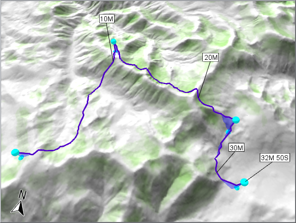 |
It may be surprising that the total travel time increases when the risky yellow box is removed. An obstacle is removed, and the new route seems worse! However, remember that the routing algorithm does not try to minimize the true travel time, but a fictional travel time including penalties in risky zones and discounts in extra-safe zones. Without the yellow box, the true travel time increases and the yellow time penalties has disappeared, so what can explain the new route? The answer must be that the new route gets larger time discounts for some extra-safe zones, and these are the green areas where the terrain offers some concealment, at least for nap-of-the-earth flight. Our color scheme is based on traffic-light symbology where red means Stop, yellow means Cautious and green means Go, so the green areas are not vegetation. However, the time discounts through the concealed areas will not be available as attributes of any output features, since they vary continuously along the route and would be hard to summarize in a useful way: the ultimate summary would be the internal route cost that guides the routing algorithm, but that cost would not mean much to a human expert.
If we finally also turn off the Concealment_SWITCHOP, we get a bare-bones routing. The AirRouteOperator is designed to generate nap-of-the-earth routes, except when passing through a high waypoint or over an airspace. But the operator does not really know why, and without awareness of the green concealed areas, it will generate a route along the central ridge:
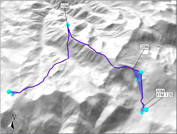 |
This is not a well-concealed route since the aircraft will be visible from both sides of the ridge, but the AirRouteOperator does not understand that flying along the ridge defeats the purpose of nap-of-the-earth flight. All it knows is that due to the AircraftType.SpeedProfile used in the sample, the aircraft flies slower when it has to climb or descend, so the high ridge is the fastest route for the middle leg, given that nap-of-the-earth flight is mandatory between waypoints.
6 Calculating Concealed Areas
We usually prefer a route that goes through concealed areas, and since the AirRouteOperator does not calculate them, something else must do that. This calculation is tricky for two reasons:
We must calculate results reasonably fast.
We don't have a precise specification of what terrain concealment means.
The speed will be less important if the results can be cached, because a common use case is that the parameters for the concealment are kept fixed while the waypoints are moved around.
The lack of a precise specification is a more fundamental problem. We can just try to emulate conventional wisdom, and before our emulation is deployed in a real system, we should get it approved by a human expert on mission planning. Here, we will describe how concealment is calculated in the sample configuration and suggest some variations.
Let us start with some basic conventional wisdom: a low-flying aircraft is concealed when it flies in a valley but exposed when it flies over a ridge. And in an early prototype, a Carmenta team tried to use the RidgeOperator to generate extra-safe valley lines and risky ridge lines for the aircraft routing. There was some success, but the RidgeOperator did not seem to give quite enough information and flexibility. For example, some more refined wisdom says that it is better to fly near but below a ridge line than in the central valley line, because the aircraft gets roughly the same concealment, and also a quick escape route over the ridge if a threat is found in the valley. The RidgeOperator cannot easily be used to generate such an offset ridge line, since the suitable offset distance depends on the sharpness of the ridge.
Instead, we think the VisibilityIndexOperator provides a solution. You may know that the visibility index for an observer position is the visible percentage of an area of interest, which can be either be explicit in the form of one or more polygons, or implicit in the form a maximal range circle or range sector around each observer position. So, a position with a low visibility index is concealed since lines of sight can be used in both directions: if our aircraft cannot see much of the ground around it, there will also be few places from which a ground-based enemy unit can see our aircraft. In other words, the terminology of the VisibilityIndexOperator is backward for our purpose: when we use the operator we must think of our aircraft as the observer and enemies as targets, although in reality it is the opposite.
After some experiments, we have found three alternative methods to use the VisibilityIndexOperator for aircraft routing. These will be described in turn, starting with the simplest method used in the sample configuration. We will also describe how you can calculate directional concealment, but that is a separate issue that can be done in the same way with all three basic methods.
A basic issue is that the visibility indexes in some way must be rescaled to sensible safety factors for the AirRouteOperator. In the sample configuration, we use a RasterConversionOperator (named RescalingRasterConvOp) to rescale the index interval from 0 to 100% to safety factors in the range 5.0 to 1.0; that is, a visibility index of 100% means no concealment and a normal safety factor of 1.0, while a visibility index of 0% means full concealment and a maximal safety factor of 5.0. The second method will use the same rescaling, but the third will use a different one. You may ask why 5.0 is the maximal safety factor here, and the answer is: why not? By varying the value, we can vary the importance of concealment and get alternative routes, but that idea is not explored further in this tutorial; instead, see the article Aircraft Routing.
We can now understand why the legend with green color ramp has two sets of numeric labels: the labels to the left show the values produced by the VisibilityIndexOperator, while the labels to the right show the rescaled values.
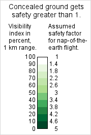 |
By the way, the legend shows the basic color ramp, but the GlobeView surface layer named Concealment blends the green colors with the hillshading and the 3D lighting, so one cannot figure out absolute values accurately from the GlobeView visualization. But one can see relative values and general trends, which should be good enough.
6.1 Concealment with the sample method: Visibility for constant AGL height
First we will describe how concealment is calculated in the sample configuration.
6.1.1 Omnidirectional concealment
A basic assumption for the sample is that we have no idea where enemies might be, so the concealment is omnidirectional. And we do not know the physical characteristics of the enemy equipment, for example its height, but the sample assumes a constant height Above Ground Level (AGL). A constant height above treetops would give similar results and be appropriate if the enemy equipment also consists of drones flying nap-of-the-earth, but the sample does not model tree heights in any case. In the VisibilityIndexOperator, the following property values have been chosen:
desiredInputResolution = 40 m, because finer resolution is much slower and accuracy is not crucial.
maxDistance = 1000 m, because this is faster than longer distances and has other advantages (see below).
pictureWidth = 360°, the default, because we model omnidirectional concealment.
rays = 8, because accuracy is not crucial, and the default value 180 is much too high when we have no targetInput.
sensorHeight = twice the vertical clearance used by the AirRouteOperator, plus an offset that will be discussed later.
targetHeight = same as the sensorHeight, because we lack more precise knowledge of enemy equipment, and this setting seems to work in practice.
As our maxDistance we should ideally use the range of enemy weapons, but we lack such information, and there could be many kinds with different ranges. The 1000 m maxDistance seems to work fine in our sample, but you can try something else: if you open the map configuration in Carmenta Studio you can increase the maxDistance to 5000 m, say, and then reload it in Carmenta Explorer. You would see a different distribution of the green areas, where valley centers appear more concealed than the slopes near the ridges:
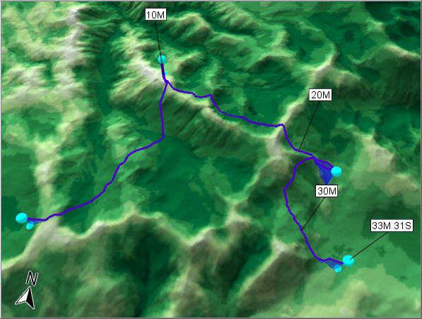 |
So, the 5000 m concealment areas do not agree with our preconceived but sensible idea that it is better to fly near but below a ridge than in the valley center. Since the 5000 m result also takes longer time to calculate, there is no reason to use it, even if the generated route did not become much different. So you can reset the maxDistance to 1000 m.
6.1.2 Directional concealment: the enemy is at a certain bearing
Let us try another variation. As you have seen, when all airspace inputs are disabled, the AirRouteOperator lets the route go along the north side of the central ridge. This should offer good concealment from an enemy south of the ridge, and probably some concealment also from an enemy north of the next ridge northward, but not much concealment from an enemy just north of the central ridge. Now, assume that we know the enemy is somewhere northeast of our route waypoints. Then, we no longer have to use an omnidirectional VisibilityIndexOperator: instead, we can set
pictureDirection = 45°, indicating northeast.
pictureWidth = 35°, say, because we do not assume the enemy is exactly at northeast.
rays = 24, because with 24 rays per revolution we are sure to get 3 sample rays inside the 35° sector.
With these settings, we get directional concealment areas where slopes facing southwest are most concealed, and the route will go on the safer side of the central ridge.
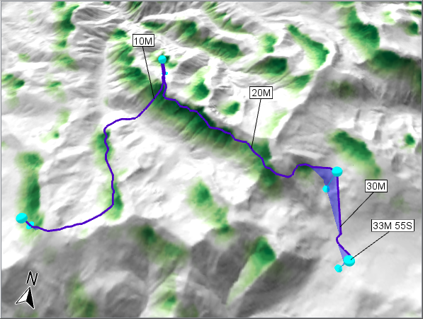 |
6.1.3 Directional concealment: the enemy is in a certain area
Another kind of directional concealment is possible, where we do not have an approximate bearing toward the enemy, but an approximate location of the enemy. If the location can be expressed as a polygon feature, it can be stored in a MemoryDataSet that is read by a ReadOperator that is used as the targetInput of the VisibilityIndexOperator. To handle such a target polygon, we should reset pictureDirection, pictureWidth and rays to their default values (which gives us 180 rays per revolution), and it makes sense to use a longer maxDistance. In the screenshot below, we have used a maxDistance of 20 km, and an enemy polygon whose longest diagonals are 4 km, and we have reduced the targetHeight to a more realistic 15 meters.
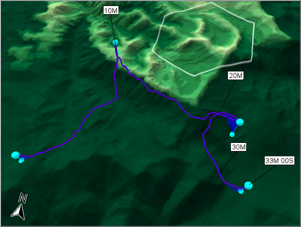 |
Now, the safest slopes are not those that are facing southwest, but the ones that face away from the enemy polygon.
But when we have an explicit enemy area, should we really conclude that an aircraft position with a low visibility index, say 5%, is well concealed? Well, it does mean that if a single enemy sensor is placed randomly in the area, the probability of a free line of sight is 5%. Unfortunately, we should not expect the enemy to place their sensors randomly, but rather at the peaks that offer the best visibility. So, it may be wiser to use a different conversion from visibility indexes to safety factors, for example where all positive indexes are converted to the normal safety factor of 1.0, while only the zero indexes are converted to a higher safety factor of 5.0.
Calculating concealment with these settings will be much slower, but the results are cached, so if the parameters and the enemy polygon can be kept fixed, you can edit the waypoints to generate new routes as fast as before.
And if the enemy area is small enough, an alternative could be to just place a sensor point feature in its middle and generate a volumetric viewshed that should be avoided. We have already seen that technique in the beginning of the tutorial (the two big eyes with red viewshed volumes).
6.2 Concealment with another method: Visibility for same MSL height
While these screenshots using the sample method have shown the flexibility of the VisibilityIndexOperator, there is a basic issue that can be questioned: the chosen sensorHeight. You may remember that the configuration uses twice the vertical clearance plus an offset. Using twice the vertical clearance can be motivated: the AirRouteOperator wants a vertical clearance above obstacles for good measure, so it should want the same vertical clearance up to the flight height that exposes the aircraft, and therefore it makes sense to pretend that the aircraft is vertical clearance higher than it really is, when calculating concealment. But if we just use twice the vertical clearance, it turns out that the route can go too near the ridge when the vertical clearance is small. In other words, an aircraft position that is too near and higher than the ridge line can be assigned a low visibility index. This is because within the short 1 km maxDistance, most of the ground beyond the ridge line is often protected by the curvature of the ridge cross section. In this situation, enemy observers beyond the 1 km could see our aircraft. Of course, that risk cannot be avoided completely, since there could always be a steep mountain that enemies could stand on just beyond our maxDistance. But at the very least, we want our aircraft to fly lower than the ridge line to protect it from horizontal lines of sight, and the method used in the sample configuration does not really guarantee that. The extra vertical offset seems to produce such routes in the Lake Tahoe area, but we cannot know for sure if it will work in a different topography, or with lower values of the vertical clearance.
A conclusion can be that the sample method calculates visibility indexes in the wrong way. It assumes that the enemies are at a constant height above ground (or possibly above treetops), but that is not exactly what we need near a ridge line. It would be better if we could assume that the enemies are always at the same altitude above Mean Sea Level (MSL) as our aircraft, for each possible position of the aircraft. This is not a realistic assumption in a literal sense, but it is a useful assumption since it concerns concealment from horizontal lines of sight, and since we hope that areas concealed according to our maxDistance will mostly be concealed also over longer distances. In other words, we want to know the visible percentage of a horizontal disk centered on the aircraft. As soon as the aircraft rises above the ridge line elevation, the disk would no longer intersect the ground and the visibility index would be 100 percent. But elsewhere, when the aircraft flies at a low height above ground along the side of a ridge, about half the disk should be underground and the visibility index should not be much higher than 50 percent.
We can in fact implement this idea, even though it was not anticipated when the VisibilityIndexOperator was designed. It would have been nice if we could use a zero targetHeight and a special setting for targetHeightType that means "Above our aircraft position", but such a setting does not really exist (the target height type can only be above ground, treetops or sea level). But there is a less obvious way: use 0° as the maximal elevation angle of lines of sight from the aircraft by setting pictureElevation = −45° and pictureHeight = 90°, and set the targetHeight to something very high, say 10 000 m. If the aircraft is now below the ridge line height, it cannot see over the ridge because it cannot lift its eyes that high, so that is what we want. But if the aircraft is higher than the ridge line, we want it to see an enemy target beyond the ridge – and indeed it can! That may be surprising when the targetHeight is so huge, but the VisibilityIndexOperator is mainly designed to look for ground-based targets, so in this situation, the operator will assume that the aircraft would see the impressive tower that the enemy target must be standing on.
With these alternative settings, we should be able to use a sensorHeight that is exactly twice the vertical clearance, without any ad hoc extra offset. If we do this to calculate omnidirectional concealment using the original 1000 m maxDistance, we can summarize the settings in this Carmenta Studio screenshot:
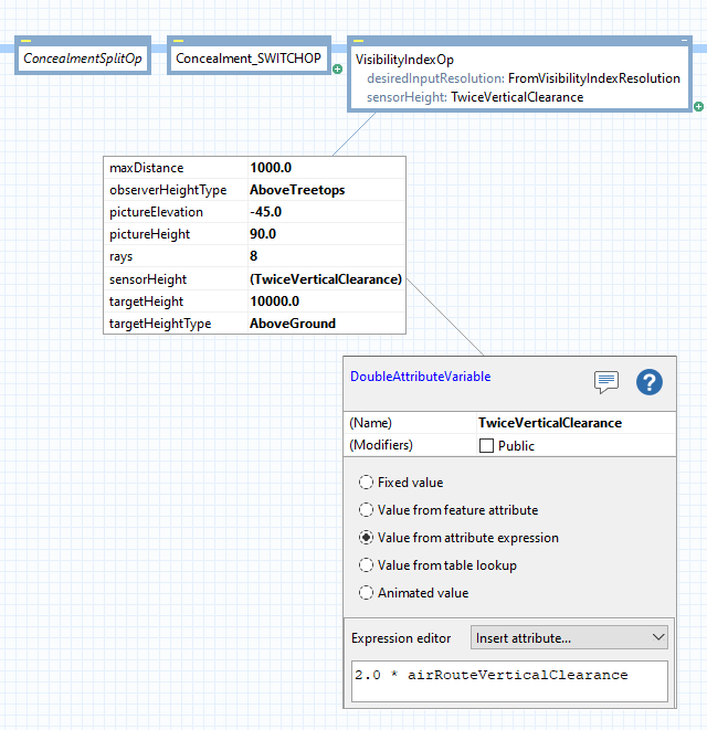 |
and we will see this result in Carmenta Explorer:
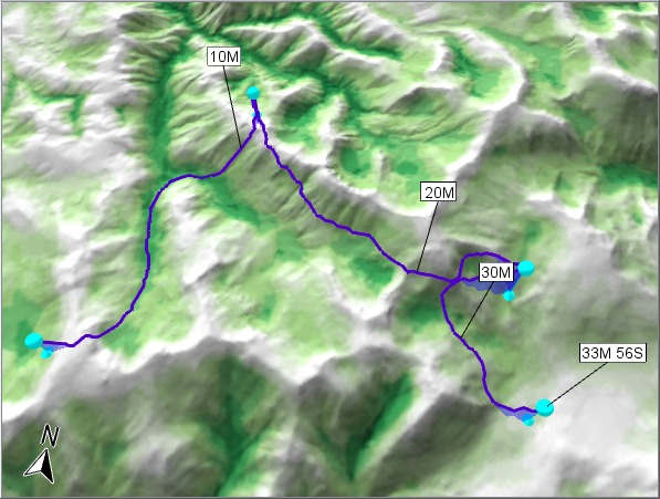 |
These are mixed results. The route does appear to go below the ridge line heights as intended, although full verification would require us to move the GlobeView camera or switch to the vertical profile display. But now it is the central valley lines that win the concealment contest. That is logical when you think about the disk geometry at the bottom of a valley, but not the result we prefer. Fortunately, the AirRouteOperator is still unwilling to let the aircraft climb and descend too much, so the route seems fairly sensible anyway – maybe the leftmost part has been too attracted to the valley center.
As a simple workaround, one could just use a cut-off; that is, give the same safety factor to all visibility indexes below some index value that is typical halfway down a ridge. Such a cut-off could be done by the current RasterConversionOperator simply by setting a maxValue property, and it would at least decrease the lure of the central valley lines.
6.3 Concealment with a third method: Visibility rate of change for same MSL height
The same-MSL-height method can be refined further. The valley centers are indeed the most concealed areas using the disk visibility idea, that is just a geometrical fact. But there is something characteristic of the visibility indexes near the ridge lines: they change suddenly over a short distance, when the aircraft position moves from being slightly below the ridge height to being slightly above, and there is no reason to think that such sudden changes can appear elsewhere. Since they indicate the boundary between half-concealed and exposed positions, it should be good to trace a route near the boundary, although for good measure the route should of course go downhill of the boundary to avoid exposure. So we want the rate of change of the visibility index: let us pipe the output from VisibilityIndexOperator through a SlopeOperator with default settings.
In ordinary default usage, a SlopeOperator gets an elevation raster and produces a slope raster. Each slope is defined as a quotient, rise over run, where rise is a vertical distance and run is a horizontal distance, except that the operator produces slope values in percent. However! The SlopeOperator can calculate rate of change for any numeric raster, since it will never notice that the raster values do not mean heights. So if the numeric raster contains visibility indexes from a VisibilityIndexOperator, the rise will be an index difference between two adjacent cells, and the run will still be the horizontal distance (in meters) between the two cells. For example, if the visibility index changes from 25% in one terrain cell to 75% in the next cell 50 meters away, the rise is 50% and the run is 50 m, so the quotient is 50% / 50m = 1.0 index percent per meter which is our rate of change, but the since the SlopeOperator will convert the quotient to percent, the output value will actually be 100 instead of 1.0. It is a bit confusing that two kinds of percentages come into play, but the main idea is just that a high rate of change means a sudden change of visibility at the boundary of the concealed areas, near a ridge, and we want to trace our route near or just downhill of that boundary.
A potential worry here is that the output format of the SlopeOperator was designed for ordinary slope values, so the output raster cells are 8-bit integers with values in the range 1 to 254, with 255 meaning Undefined. In the general case when the input rasters are not ordinary elevations, that integer range may or may not be appropriate for the output, but it turns out that we are lucky in our case: the range of output values goes from 0 to about 80 or 90, at least for the VisibilityIndexOperator settings used in the sample configuration, so the 254 limit does not cause loss of information, and the rounding to integers should be harmless since the VisibilityIndexOperator and the SlopeOperator are not perfectly accurate anyway.
Of course, we have to modify our rescaling RasterConversionOperator, since its input raster now has a different meaning. You may recall that until now, we have rescaled a visibility index of 100% to 1.0 (normal background safety) and a visibility index of 0% to the safety factor 5.0 (maximal safety factor from concealment, somewhat arbitrarily chosen); so, lower values mean less visibility but higher safety. Now we need something different: for example, we can map a rate of change of 0 percent to the safety factor 1.0, and more generally each rate of change value of s percent to the safety factor 1.0 + s/10. The modifications to the operator chain are shown below. Note that it is now important that the rescaling RasterConversionOperator also converts to Float, because keeping the rescaled values as integers would be too lossy.
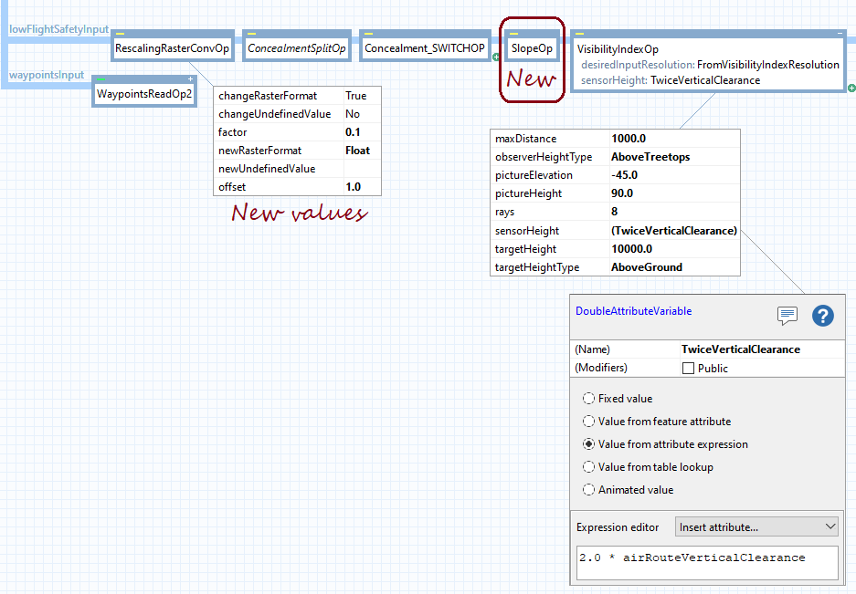 |
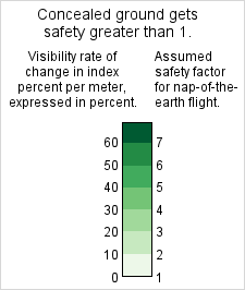
If we want to continue displaying preferred areas in darker green colors, we need a revised color table in our raster visualizer. At the very least, we must reverse the order of the colors since higher slope values are more preferred. In our sample, it also turns out that not many slope values become higher than 60%, so it should be enough with seven colors instead of ten, as shown in this revised legend:
 |
And the result is striking:
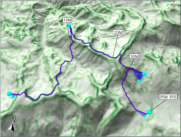 |
We see distinct pairs of green lines at opposite sides of each ridge. In the upper left, we can see some line pairs that are farther apart because the ridge is less sharp, which makes sense. Finally, we have implemented a calculation that agrees with our preconceived but sensible ideas.
Well, maybe not quite. The route is attracted to the green lines, but as mentioned above, it could be wise to let the aircraft go just downhill of them, for good measure. We could choose to ignore that refinement, since the green lines were calculated assuming an aircraft height above treetops that is twice the vertical clearance, as discussed in sections 6.1 and 6.2. In other words, the green lines indicate where an aircraft that is vertical clearance above the route line would begin to be exposed, but since we intend to fly along the route line, we already have a vertical clearance up to the exposed altitude. However, if we do want the refinement, it is not obvious how to make the route attracted to the downhill side of the green lines. It is easier to force the green lines themselves a bit downhill by again using an extra height offset in the sensorHeight. Or we could increase the maximal elevation angle for the lines of sight: instead of using pictureElevation = −45° and pictureHeight = 90°, we could use pictureElevation = −40° and pictureHeight = 100°, say, which would raise the maximal elevation angle to 10°. It may be hard to find the optimal values for the extra height offset or the maximal elevation angle, but as long as they are positive we can feel some confidence, since we started with green lines on the boundary of concealment and then moved them further into concealment. When using the basic method in the sample configuration, we cannot be as confident, since the extra height offset in the basic method must be not only positive but large enough, for an unknown value of "enough".
However, these tricks to move the green lines downhill will not work in the special case of a precipice, where elevations change abruptly between a valley floor and a plateau. Each rate-of-change value is calculated from a set of 3 by 3 elevation cells, so we can expect that the green lines would then be centered on the precipice line, regardless of any extra height offset or raised maximal elevation angle. But in any case, the AirRouteOperator cannot handle a precipice well: see the section Limitations in the article Aircraft Routing.
7 Acknowledgments
The green color ramp comes from ColorBrewer.org.