Terrain Vehicle Analysis
There are three operators that, in various ways, calculate how terrain vehicles can interact with the terrain and the roads.
The TerrainSpeedOperator calculates local speed, on-road or off-road.
The TerrainRouteOperator calculates a route through a given list of waypoints.
The TerrainAccessOperator calculates accessibility (travel times) from a starting position; this is also known as isochrones or omnidirectional route analysis.
The operators have many properties in common, which are inherited from the abstract base class TerrainMobilityOperator.
1 Overview of Operators
The three operators use a specified TerrainVehicleType as well as inputs giving road and terrain information, and an optional input giving restricted areas.
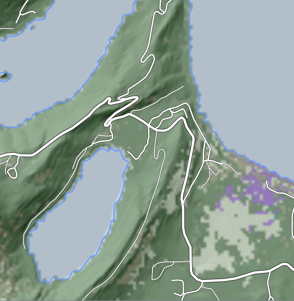
Before we give example screenshots from the operators, we display a common background map. The examples will use an amphibious vehicle type.
 |
1.1 Speed
The TerrainSpeedOperator gives for each point in the terrain the possible speed of the vehicle type. The terrain speeds will be output in km/h in the form of an integer raster.
The output will also contain copies of the road features, which have got their vehicle speed as a new attribute. However, since the road speed mainly depends on the road class which normally can be seen in the basic road visualization (the line width in our example), the line output is less interesting than the terrain speed raster.
It is often enough to use a single color to display only the "no go" areas where the speed is zero, and rely on the other operators for further analysis.
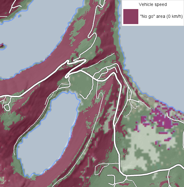 |
The terrain_speed_operator.px sample configuration uses a second color for "slow go" areas. However, it can be challenging to use colors for the terrain speeds, since they either blend with or obscure the background map. The class documentation for the operator shows an alternative visualization where the terrain speed raster is converted to polygons that can be displayed with black striped patterns.
1.2 Routes
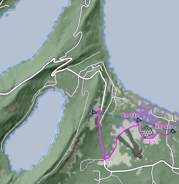
The TerrainRouteOperator gives, for a list of waypoints, the fastest route that passes through them all.
 |
1.3 Accessibility
The TerrainAccessOperator takes a starting position, and gives for each off-road or on-road point its accessibility, defined as the shortest travel time from the start position to the point. The output will be a raster feature for the off-road accessibility, and a set of many short line features for the on-road accessibility.
The starting position is usually a point feature, but it could also be a line feature or the entire road network.
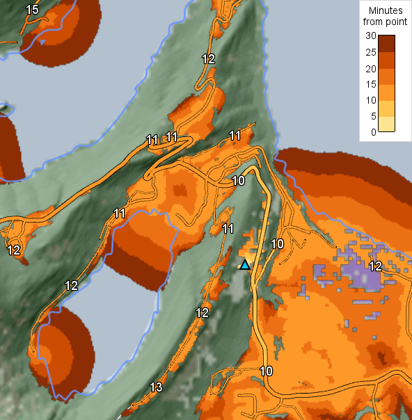 |
It is possible to place accessibility labels also in terrain by using an IsolineOperator, as is done in the terrain_access_operator.px configuration sample.
2 Restricted Areas
All the operators have an optional input giving restricted areas, which normally cannot be entered at all. However, the TerrainRouteOperator can be configured to allow soft restrictions: the operator will be more or less reluctant to let the route go through a softly restricted area, based on a TerrainRouteOperator.RestrictedAreaSafety value between 0 and 1.
3 Road Modelling
The three operators use a common road model, although some of its details are ignored by the TerrainSpeedOperator. There are operator properties that control how road feature attributes are interpreted to deduce
the road class: an integer giving the quality of the road;
the RoadType: bridge, tunnel or ferry route, or ground road with or without terrain access;
the maximal allowed width, height, length and weight of a vehicle on the road;
the RoadDirectionality: two-way or one-way, and of course the allowed direction for one-way roads.
It is assumed that road features are connected to other road features only at their end points, so an interior node of a road feature is never treated as a connection; this assumption is valid for many but not all road databases. A connection requires that two roads meet end to end, such that the x and y coordinates of the end points are equal within a 0.1 mm tolerance. The z coordinate is not tested, since it is usually not available in road databases. So if two road nodes are separated by 10 cm, say, or if at least one of them is an interior node, there will be no direct connection between them. Still, we are dealing with terrain vehicles here, so if the RoadType values of both roads allow terrain access and if the terrain is trafficable, the vehicle will be able to bridge the gap by a short detour in terrain. (The detour must go via the nearest center of a terrain raster cell, so the route geometry would get a tiny spike, which can serve as a visual indication of the terrain detour).
Turn restrictions in intersections cannot be handled if they are represented as road attributes. They can be handled if they are instead represented by the road network topology, see Tim Hirrel, Turn Restrictions Simplified, but the topology representation is rarely used. Also, to get the operators to respect topological turn restrictions, one must ensure that the operators do not treat the intersection roads as having the RoadType value that allows terrain access, because in that case, the operators could let the vehicle leave the road just before the intersection and take a short terrain path to any other road from the intersection.
When the road type allows terrain access, a route through terrain can cross the road anywhere the terrain is trafficable, but going from terrain onto the road, or vice versa, is only possible on a node of the road line geometry – with a few exceptions. So, if many road line edges are much longer than the elevation resolution, the results may look more natural if the road lines are densified with intermediate nodes. See RoadType for a tip on how to densify roads.
The only kind of weight restriction that can be handled by the operators is a maximal vehicle weight for each road feature. But weight restrictions can be very complicated and may differ between countries:
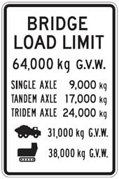 |
Also, weight restrictions designed for civilian traffic can be difficult to apply to military vehicles:
A.J. MacDonald, F.M. Bartlett and R. Gordon Wight. Probabilistic gross vehicle weights and associated axle loads for military vehicles in bridge evaluation and code calibration. Advances in Military Technology 12(1), pages 129–145, 2017.
So you may need to use your own application logic to identify the input road features that are too weak for your vehicle type. It would be tempting to try to use a FilterOperator or a custom operator to remove any input road that is too weak, but that would be incorrect if the RoadType represents a ground road without terrain access: even if too weak to drive on, such a road has a role to fill as a barrier in the terrain, since no vehicle should cross it from terrain to the other side. Therefore the operator must receive the road, but you can use an AttributeOperator or a custom operator to manipulate the road attributes that control the road class, so that a too weak road gets a road class of 99999, which would cause the road speed to become zero (unless the TerrainVehicleType.RoadSpeeds list has 99999 entries).
4 Terrain Classification System
To describe terrain conditions, we use a terrain classification system developed in Sweden by the army and the forestry industry.
Staffan Berg. "Terrängtypsschema för skogsarbete". SkogForsk (Forestry Research Institute of Sweden), 1982; this Swedish version is available online. An English version has also been published: Terrain classification system for forestry work, 1992, which can be ordered from SkogForsk.
The full classification system contains seven terrain factors, each of which is graded on a scale from class 1 (best) to class 5 (worst). Carmenta uses only the three most important factors.
Ground Condition | Surface Structure | Slope | |
|---|---|---|---|
1 | very strong | very even | 0 – 10% |
2 | strong | even | 10 – 20% |
3 | average | somewhat uneven | 20 – 33% |
4 | weak | uneven | 33 – 50% |
5 | very weak | very uneven | more than 50% |
The ground condition class describes the soil strength, which can be estimated from soil type and either forest type or soil moisture and humidity. The operators have a groundConditionInput that gives a raster of these classes, 1 to 5 on land, or 6 for water.
The surface structure class is a statistical measure of the terrain roughness on a detailed level, and depends on the frequency and heights of rocks, boulders, soil mounds and cavities. The operators have a surfaceStructureInput that gives a raster of these classes, 1 to 5.
For slopes, the operators simply have an elevationInput that gives a raster of elevations, from which slopes are calculated. However, the five slope classes are used when describing vehicle properties.
5 Describing Vehicle Properties
To use the operators, you must define one or more instances of the class TerrainVehicleType that describes the vehicle properties. Carmenta Engine does not contain a library of predefined instances, although there are two example instances given in the three sample map configurations for the operators.
Most properties of a TerrainVehicleType have a straightforward type:
height: a Double giving the height in meters.
length: a Double giving the length in meters.
roadSpeeds: a collection of Double elements, giving the speed on roads of class 1, 2, 3, etc., in km/h.
sideSlopeMax: a Double giving the maximal side slope, dimensionless.
slopeMax: a Double giving the maximal forward slope, dimensionless.
snowDepthMax: a Double giving the maximal snow depth in meters.
waterSpeed: a Double giving the speed in water in km/h.
weight: a Double giving the weight in tonnes.
width: a Double giving the width in meters.
But the main property is the landSpeeds property, which gives the vehicle speed in various kinds of terrain. Since each of the three terrain factors in the classification scheme can take one of 5 values, there are 5 × 5 × 5 = 125 possible terrain types, which can be regarded as forming a cube:
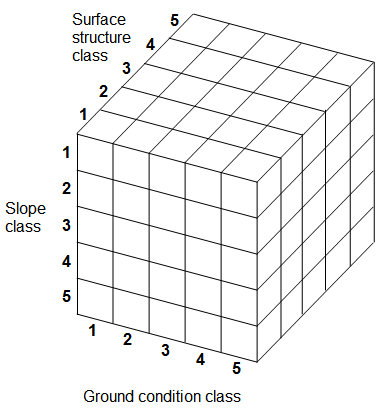 |
Each of these terrain types needs a specified speed. This design is based on
Börje Aulin. Datormodell för simulering av fordonskolonners marsch på väg och i terräng, in Swedish. ("Computer model for simulating the movement of vehicle columns on roads and in terrain"). Försvarets Forskningsanstalt avd. 2 (Swedish Defence Research Agency), Report A 2549-F7, December 1971.
Carmenta Engine represents the speed cube as a collection of TerrainSpeed structures, each of which specifies a ground condition class, a surface structure class, a slope class, and the corresponding vehicle speed. It is cumbersome to use Carmenta Studio to write all these structures, so it is better that you make an application GUI for vehicle specifications.
5.1 Example user interface for defining terrain speeds
As an example, here is a snapshot of the landSpeeds interface of an application developed for the Swedish Armed Forces.
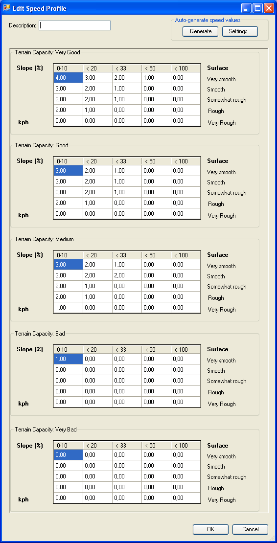 |
The interface is based on the conceptual cube of 5 × 5 × 5 speeds, but the cube has been sliced into five squares, each containing 5 × 5 speeds. Compared to the Carmenta Studio interface, this design gives a better overview and requires less typing.
Still, typing in 125 speeds is tedious, so the interface also allows generating all terrain speeds automatically from the first speed – for the best terrain – and six special parameters, which are available via the Settings... button.
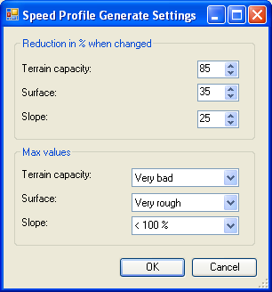 |
The first parameter is 85 percent in the screenshot. This means that if you know the speed in one terrain type, then the speed is 85 percent of that in the terrain type that has the next worse ground-condition class.
The second parameter is 35 percent in the screenshot. This means that if you know the speed in one terrain type, then the speed is 35 percent of that in the terrain type that has the next worse surface-structure class.
The third parameter is 25 percent in the screenshot. This means that if you know the speed in one terrain type, then the speed is 25 percent of that in the terrain type that has the next worse slope class.
The final three max values gives, for each terrain factor, the worst class that the vehicle can handle. In the screenshot, the vehicle can handle the worst possible class of all three terrain factors, so these max values do not restrict the generated speeds. Otherwise, the generated speed would be reduced to zero in every terrain type where at least one terrain factor is worse than the worst that can be handled.
If we use the parameters of the screenshot and start with a best terrain speed of 50 km/h, then pressing "Generate" will fill the large table with these values:
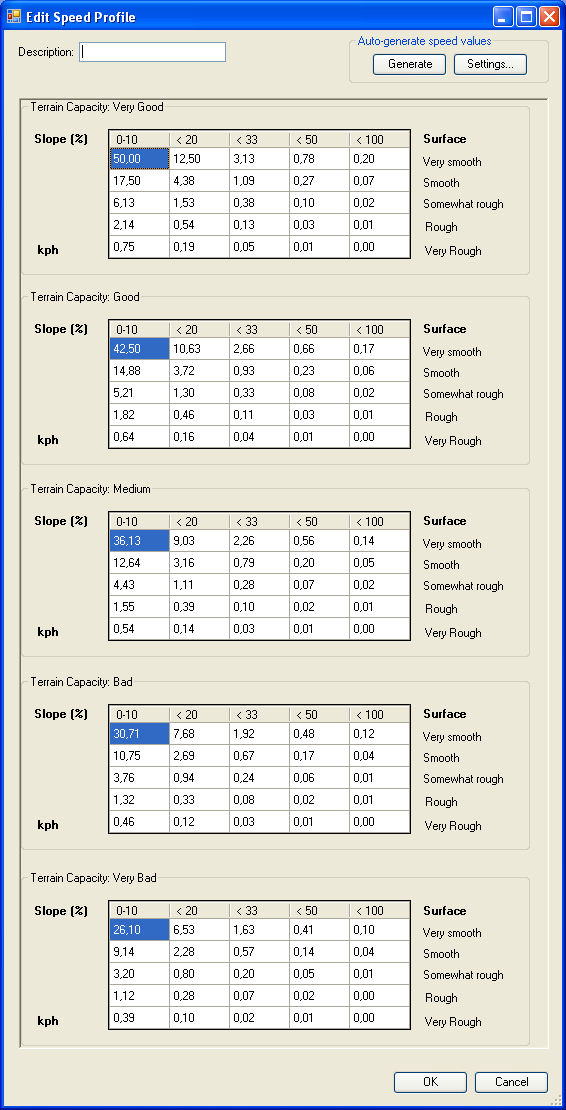 |
In this way, the vehicle expert only has to enter seven parameters to describe the terrain speeds of a vehicle. He or she can then study the generated table to see the effects of the parameters, and can choose to edit some of the generated speeds. However, the simple seven-parameter description is not supported directly by Carmenta Engine, since there are several possible ways to design such a simplified vehicle description, and Carmenta does not want to prejudge which one is best.
6 Finding Terrain Data
Finding useful terrain data can be a problem. Elevation data are often available, but the ground condition (soil strength) and the surface structure (detailed roughness) are harder to find. Berg's handbook for the Terrain Classification System is mainly intended for forestry work, and simply suggests that you walk around in the terrain and take notes.
Modern elevation rasters can have a high horizontal resolution, about 1 meter, and it is easy to think that using such a high resolution would make the analysis more accurate. But this is not true, because the analysis assumes that the terrain vehicle is small compared to the elevation resolution. For example, let us say we have one-meter horizontal resolution, and that the terrain rises one meter from one terrain cell to the next. The calculated slope would then be 100 percent, which most terrain vehicles cannot handle – but in this case, if the slope does not continue further, it would be similar to a one meter high obstacle, which many terrain vehicles can handle. The elevation resolution recommended by Berg's handbook is 25 meters, but we expect that values in the range 10 to 50 meters can also work.
A better use for one-meter elevation rasters could be to use them to calculate the surface structure in the form of, say, 25 meter surface-structure rasters. However, because of the way that the surface-structure classes are defined in Berg's handbook, it is not obvious how to make this calculation - see next section.
The ground conditions can be derived from soil type data, which is sometimes available. But a problem is that the soil strength depends on both soil type and soil moisture, and the moisture is seasonal, and can even change in one day if it has been raining heavily. And of course, a swamp can freeze in winter.
7 Interpreting the Terrain Factors
There are many other models for analyzing terrain vehicle mobility. Paul Birkel has written a survey about four such models, and a more recent article by Heštera and Pahernik surveys twenty-five models.
Paul A. Birkel. Terrain trafficability in modeling and simulation. Technical Paper SEDRIS – 2003 – 1.
Hrvoje Heštera and Mladen Pahernik. Physical-geographic factors of terrain trafficability of military vehicles according to Western World methodologies. Hrvatski Geografski Glasnik/Croatian Geographical Bulletin 80/2, pages 5–31, 2018.
So one can wonder how tightly Carmenta Engine is tied to using the Swedish terrain classification system.
For the slope classification, the ties are fairly tight. This is because the operators do not take a slope raster as input, but take an elevation raster and compute the slope by themselves. This design allows the operators to treat a forward slope and a side slope in different ways, which should give a better modelling, but the operators have to understand what the slope classes mean. That is, the slope classes that are used in a TerrainVehicleType.LandSpeeds must stand for the slope value intervals defined in the Swedish classification system – you cannot pretend that they have a different meaning. On the other hand, the operators do not really assume one constant speed for all slopes between 0 and 10 percent, and then a different speed for all slopes between 10 and 20 percent, etc. Since the operators know what the slope classes mean, they will interpolate instead. Therefore it could be possible, if not easy, to translate a vehicle description created for a different slope class system into a TerrainVehicleType.
For the ground condition classes and the surface structure classes, the ties to the Swedish system are not so tight. This is because the operators do not really know what these classes mean; they are just numbers used to look up terrain speeds in the TerrainVehicleType.LandSpeeds. So, it is not necessary to follow the Swedish definitions of these terrain factors – you can modify the definitions as you wish, but the people who define terrain vehicle types must use the same definitions as the people who prepare raster data for these terrain factors. Of course, the flexibility is limited: you can define your own two terrain factors that could mean whatever you like, but you cannot use more than two terrain factors (apart from slope), and they cannot take more than five different values.
7.1 Reinterpreting the surface structure classes
In fact, we think it will always be necessary to deviate from the strict definition of surface structure in Berg's handbook, since it does not include tree stumps, fallen trees, or any other vegetation, which are instead represented by a separate terrain factor. The Swedish army sometimes classifies vehicles relative to three subfactors of surface structure: point obstacles like in Berg's handbook, linear obstacles like ditches, and vegetation. But we think that it would be infeasible to allow more than the three current terrain factors when defining a TerrainVehicleType. So we suggest that you redefine the surface structure classes of Carmenta Engine to represent something more general:
the density and impact of any obstacles that impede a terrain vehicle, apart from slope and soil strength.
But it is hard to say how this density and impact should be quantified and classified. If you have access to 1-meter elevation data, including the effect of vegetation, or if you have access to detailed point cloud data from aerial laser measurements, it may be possible for you to choose a computational method to produce a measure of roughness that can be used. The problem is that there are many ways to compute roughness:
Terrain Roughness – 13 Ways. In GIS 4 Geomorphology, Copyright 2016 Skye Cooley.
7.2 Reinterpreting the ground condition classes
It might also be useful to widen the meaning of the ground condition classes. Berg's handbook considers only the bearing capacity, but the survey by Heštera and Pahernik mentions other soil properties like shear strength, slipperiness and stickiness, so it might be better to let the ground condition input represent some kind of average soil quality.
The soil types are not seasonal like soil moisture and ground frost, but there are many different systems for classifying soils, and the classifications used in some soil databases are not detailed enough to predict trafficability. A report by García-Gaines and Frankenstein develops a approximate mapping from the simpler USDA (U.S. Department of Agriculture) system to the more detailed USCS system (Unified Soil Classification System), and also gives an overview of the various kinds of soil classification systems, and an introduction to some major soil databases.
Rubén A. Garcia-Gaines and Susan Frankenstein. USCS and the USDA soil classification system: Development of a mapping scheme. Technical report ERDC/CRREL TR-15-4, Cold Regions Research and Engineering Laboratory, Vicksburg, Mississippi, 2015.
8 Further Reading
There is an entire journal devoted to the interactions between vehicles and terrain:
published on behalf of the
which also organizes conferences etc.