Aircraft Routing
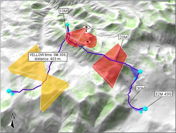
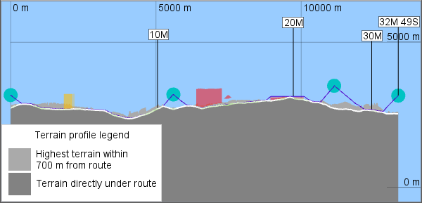
The AirRouteOperator generates a flight route between given waypoints for an aircraft, avoiding restricted airspaces and exploiting terrain for concealment, using an instance of AircraftType that describes the aircraft properties. In practice, the aircraft type should be a highly maneuverable rotary-wing aircraft, typically a drone.
 |
 |
1 Multiple Objectives: Speed and Safety
The AirRouteOperator balances two conflicting objectives: speed and safety.
A basic assumption is that the aircraft is safer where it is concealed by terrain, so it is better to fly low, and the operator will generate a nap-of-the-earth route except where the aircraft has to reach a high waypoint or fly over a restricted airspace. You can control the vertical clearance above treetops for the nap-of-the-earth parts, see AirRouteOperator.VerticalClearance, and the preferred climb and descent angles used elsewhere, see AircraftType.PreferredClimbAngle and AircraftType.PreferredDescentAngle. These settings directly affect the balance between speed and safety, since steeper climb and descent angles and a smaller vertical clearance can give better concealment but increase the travel time. And the values in the AircraftType.SpeedProfile also affect the speed/safety balance, because the maximal speed of an aircraft usually differs from the safer speed that gives the longest airborne distance.
Apart from generating nap-of-the-earth flight, the AirRouteOperator does not know about terrain concealment and other safety issues, so it cannot calculate safety by itself, but its route planning can be controlled via input features that carry safety information.
Balancing speed and safety is an example of multi-objective optimization, which is complicated. Even if each objective can be described by a number that shall be minimized or maximized, there is no definite way to compare numbers of different kinds: think of the objectives as different currencies that have no official exchange rates. This makes it hard to rank the solutions. Well, some pairs of solutions can be ranked anyway: if solution A is better than solution B in one objective and at least as good in all other objectives, then it is a no-brainer that A is preferable and we say that A dominates B. But if A is better than C in one objective while C is better than A in some other, it is not obvious whether A or C should be preferred. The results that are not dominated by any others are called nondominated or Pareto optimal, and there can be many of them, even infinitely many. So, one approach to multi-objective optimization is to let the software produce a suitably large subset of the Pareto optimal solutions, and then let a human expert choose between them.
In our case, travel time is an objective that is easy to define, but safety is harder: ultimately, we are concerned about the probability of mission success, but it would be hard to calculate and combine risks in terms of probabilities. So the AirRouteOperator uses a different approach for simplicity. To use the operator, you must explicitly define local risks in various zones (whose possible geometries are described further down). Each zone risk must be represented by a safety factor that represents an explicit exchange rate between safety and speed. In this way, the routing problem is scalarized to single-objective optimization: the AirRouteOperator will just search for the route of the minimal cost which is an adjusted or fictional travel time, consisting of:
true travel time,
plus time penalties from unsafe zones,
minus time discounts from extra-safe zones.
The AirRouteOperator will output only one route for each list of input waypoints. Your application can still try to find alternative routes by tweaking the safety factors and using the AirRouteOperator several times; the tweaking could either be automated via some application logic or controlled by a human decision maker. Note that in this use case, the AirRouteOperator does not need to be connected directly to a View, since your application can call the Operator.GetFeatures method instead. See also the section below, "Getting alternative routes from one update".
Unfortunately, there can exist Pareto optimal routes that cannot be found by any amount of tweaking; that is a drawback of scalarization with weighted sums. For example, if the shortest route would go straight through the center of a cylindrical risky zone, it is possible that any generated route will either go straight through the center or else avoid the zone completely, while compromise routes that pass through the zone off-center could be impossible to generate.
2 Safety Factors
A safety factor must be non-negative:
0.0 indicates a no-go zone,
a value between 0.0 and 1.0 represents a risky zone,
1.0 represents a neutral zone,
a value greater than 1.0 represents an extra-safe zone.
Inside a zone, the safety value will be multiplied with the aircraft speed giving a fictional speed for the route optimization, which tries to find the route of the shortest fictional travel time. In other words, a safety value less than 1.0 gives a time penalty, while a safety value greater than 1.0 gives a time discount. For example, if the safety is 0.25, each true minute in the zone counts as 4 minutes, so a one-minute shortcut through such a risky area is preferred only if the detour around it would take at least 4 minutes.
When zones overlap, their safety values will be multiplied together.
3 Zone Geometries
The input zones can be of two kinds:
Airspace features come from the AirRouteOperator.AirspaceInput and can either be extruded polygons, lines or points, or else volume-encoding rasters from a LineOfSightOperator or an AirspaceCoverageOperator. Each airspace feature can have a name and a single safety factor, by default zero, controlled via AirRouteOperator.AirspaceSafety.
An optional low-flight safety raster comes from the AirRouteOperator.LowFlightSafetyInput and contains cell values that represent local safety factors at the nap-of-the-earth height.
The safety factors for airspaces can represent any kind of risk. In theory, so can the safety factors in the low-flight safety raster, but the intention is that they represent terrain concealment, and that is why they are used only at nap-of-the-earth height. At higher flight altitudes, a basic non-concealed safety factor is used instead, the AirRouteOperator.HighFlightSafety, by default 1.0.
A convenient way to calculate terrain concealment at nap-of-the-earth height is to use a VisibilityIndexOperator, although it can be difficult to calibrate its settings, and the cell values in its output raster will have to be rescaled. This is discussed in detail in the Aircraft Routing Tutorial.
4 Getting Alternative Routes from one Update
As noted above, the safety for each airspace is controlled via the AirRouteOperator.AirspaceSafety. This is an attribute variable that can depend on attributes from two kinds of input features: both the airspace feature and the current feature from AirRouteOperator.WaypointsInput (it can also depend on View.UpdateAttributes, like most attribute variables). The dependency on two kinds of input features is unusual but makes sense here:
Different airspace features may need different safety factors because they represent different kinds of risk. Such distinctions can be controlled via attributes on the airspace features.
The safety factors can also indicate the overall desired balance between safety and speed. That balance can be controlled by an attribute of the feature from AirRouteOperator.WaypointsInput.
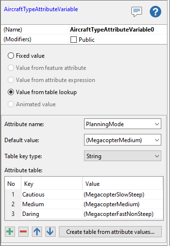
This design is useful when you want to tweak the safety values to generate several alternative routes. An obvious way to get alternatives is to use the AirRouteOperator in several updates, say three: one with a daring balance where fast and risky routes are preferred, one with a cautious balance where slow and safe routes are preferred, and one happy medium. But a better way is possible: since the balance can be controlled by an attribute of the waypoints feature, it should be more efficient to send three different features to the AirRouteOperator.WaypointsInput in a single update (or a single call to Operator.GetFeatures), since some of the input processing can be shared. The three features should have the same list of waypoints (the same line geometry) but different values for an attribute that affects the airspace safety factors and thus the overall speed/safety balance. For example, there could be a waypoints feature attribute PlanningMode with the possible values "Daring", "Medium" and "Cautious".
You could also let such a PlanningMode affect how the aircraft flies, because the AirRouteOperator.AircraftType property is an attribute variable that can evaluate to different instances of AircraftType depending on the PlanningMode. For example, the "Daring" mode should use smaller preferred climb and descent angles in its AircraftType instance, as well as faster speeds in the speedProfile. That is, in a "Cautious" or "Medium" mode the aircraft should not fly as fast as possible, because a more efficient slower speed can give a longer airborne distance, reducing the risk that the battery runs out.
 |
On the other hand, the safety factors in the AirRouteOperator.LowFlightSafetyInput cannot be controlled by feature attributes, so if you want to produce alternative routes based on different importance of concealment or using different ways to calculate concealment, you have to use the basic approach with many updates (or many calls to Operator.GetFeatures).
5 Limitations
The AirRouteOperator is mainly designed for terrain and sparse airspaces. For performance reasons, the operator does not explore all possibilities in 3D space: for example, if one airspace is above another with a gap between, the operator will normally not try to use the gap, but will try to go under, over or around both airspaces. However, if the highest airspace is given a top elevation higher than the maximum altitude of the aircraft, then the operator knows that the aircraft cannot go over both airspaces, and may then use the gap.
5.1 Horizontal and vertical resolution
The analysis uses the horizontal resolution of the incoming elevation raster, which to some extent can be controlled via the AirRouteOperator.DesiredResolution. Airspaces based on vector data will be rasterized to this resolution.
The vertical resolution is not explicitly defined and can depend on context. When the operator checks whether some parts of the route are inside an airspace, it will do so only at the center of each elevation raster cell that the route goes through. So if the route segment between two adjacent elevation cells is steep, the operator could fail to notice that the segment passes through a thin forbidden airspace. Such a steep route segment can have two causes, either a steep leg or steep terrain.
A steep leg. The straight line between two adjacent waypoints could be steep. Since this may be a common situation, the operator will give up and just return a placeholder route feature that indicates failure for each leg with a straight-line climb or descent angle greater than 70°. This means that the vertical resolution in this situation will be at most 3.9 times coarser than the horizontal one. That is, if the elevation raster has square cells with side s, then the operator can let the route pass through a forbidden airspace with a thickness up to 3.9s (because sqrt(2)*tan(70°) = 3.9). To avoid such a result, you can use application logic to ensure that airspaces based on vector data have a thickness (top-to-bottom distance) of at least 3.9 times the horizontal resolution.
Steep terrain. The terrain could be steep in an area where the operator generates a nap-of-the-earth route. In this case, there is no built-in absolute limit of 70° steepness, but you can enforce such a limit by letting the AircraftType.SpeedProfile assign a zero speed to any climb angle greater than 70° or less than −70°. Such a limit will not cause a direct failure when steeper terrain is found, so you can hope that the operator finds a less steep detour.
When it is the terrain that is steep, the worst case of a long precipice gives you no ideal option. If your speed profile allows vertical flight, the generated route may change altitude abruptly between two adjacent elevation cells as the precipice is passed, in which case the route may pass through a forbidden airspace also if it is thicker than 3.9 times the horizontal resolution. On the other hand, if your speed profile does not allow climbing or descending steeper than the 70° limit, then the precipice can form an impenetrable barrier, which could be too restrictive.
If the waypoints are placed so that the aircraft does not need to cross the precipice line, but should travel along it, then the AirRouteOperator will have another problem. Flying vertical clearance above the plateau would be too exposed, but flying vertical clearance above the valley floor would be unnecessarily low. The preferred route would often go near the plateau, lower than its elevation by vertical clearance, but such a route cannot be generated, since the route is constrained to go vertical clearance above some ground (except to reach a high waypoint or fly over an airspace).
In terrain where long precipices are common, a workaround might be to preprocess the elevation input to make each precipice less steep, either by some custom operator or via some built-in ones. For example, it might work to use a first ResampleOperator to downsample the elevations with the NearestNeighbor resample method, and then a second ResampleOperator to upsample them to the original resolution with the Interpolate resample method.
6 The Tutorial
To learn more, see the Aircraft Routing Tutorial.