Carmenta Studio User's Guide
Carmenta Studio is a visual map configuration editor for Carmenta Engine. A map configuration describes what data should be read, how the data should be processed and how it should be visualized; it describes the structure of a map in terms of Carmenta Engine objects like Views, Datasets, Layers, Colors, LineStyles, etc. A map configuration is created and stored by Carmenta Studio as a single file with the "px" file extension. The configuration file can be used by an application at runtime to create and display a map. Although a text editor can be used to create the configuration file, using Carmenta Studio has a number of advantages:
The maps can easily be explored using the Carmenta Engine map viewer, Carmenta Explorer. For more information see Carmenta Explorer User's Guide.
The structure of a configuration is displayed as a dataflow diagram, which makes it easy to grasp.
Parts of existing maps can be reused and recombined to form new configurations by direct manipulation of the dataflow diagrams.
Custom editors are available for certain objects, such as colors and variables that control how the maps are visualized.
All classes and system resources are easily accessible.
The tutorial Basic Vector Configuration Tutorial is a useful complement to this guide.
Carmenta Studio has an elaborate GUI with internal panes, tables and a toolbar. It has a tolerant attitude towards objects defined incorrectly and strives to allow anything with roughly the correct syntax to be read as well as saved. Other significant features include context sensitive help, support for external objects (imported files) and system resources.
Carmenta Studio is a Java application, which runs on OpenJDK 12.0.2 binaries downloaded from AdoptOpenJDK. These binaries are bundled with the Carmenta Engine SDK and Carmenta Studio installations, so you don't need to install a separate Java Runtime Environment to use Carmenta Studio. Please see OpenJDK license for the license terms.
Getting Started
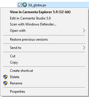
Start Carmenta Studio from the system start menu or by right-clicking a configuration file (with the "px" file extension) in a file explorer window and choose "Edit in Carmenta Studio".
 |
The User Interface
This section gives an overview of the components of the user interface. The terminology introduced here is used throughout the rest of the guide.
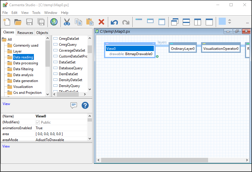
Carmenta Studio's main window is shown in Figure 2. It has a menu bar and a toolbar at the top, and a status bar at the bottom. To the left is a tabbed pane called the index pane, which has three different indices, Classes, Resources and Objects. Below the index pane is the object editor area, where the currently selected object can be edited using an appropriate editor. At the center is a large desktop panel containing dataflow windows for the open configuration files.
 |
The status bar is used to display various kinds of informational messages.
The work procedure in Carmenta Studio is really easy, an object (often called a node) is created by a drag and drop procedure of a class from the class index to the dataflow window. The object's properties can then be defined in the object editor.
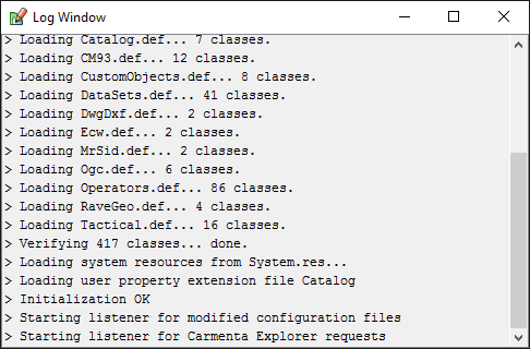
The log window (Figure 3) is a scrollable text window where important events and errors are logged. During initialization Carmenta Studio adds a number of messages to the log window. If an error occurs during startup, the log window is opened so the user can inspect the cause of the problem. The log window can be reopened from the View menu, by choosing "Show Log Window".
 |
Selections
You can select one item at a time in Carmenta Studio. The selected object can be an object (in a configuration file), a class, a system resource, or a configuration. The currently active configuration, which is the target of some menu commands, is the selected configuration or the one containing the selected object.
You can select a configuration by clicking on the background of a dataflow window or by clicking on the filename in the Objects index which is a part of the index pane. To clear the selection, click on the background of the object or class index. All dataflow views of a selected object are highlighted.
Drag and Drop
Carmenta Studio relies on drag and drop gestures for higher level editing, such as moving and copying objects. Three modifier keys are used: Ctrl means "copy," Alt means "create reference", and Shift means "drag sub-tree". The described drag and drop operations use the left mouse button. You can also use drag and drop using the right mouse button.
At the right edge of the toolbar is an object shelf, which can be used as a visual clipboard for drag and drop operations.
Menus and Tools
Carmenta Studio has a menu bar with six menus where nearly all commands are listed. Some of the more frequently used commands can also be found on the toolbar. A few object-centric commands are only available on the popup menu for objects or by clicking in certain areas. This section describes the commands as they are organized on the menus. It also introduces the object shelf, which is located on the toolbar.
File Menu
The New command creates an empty configuration with a default name. The new configuration is selected and a dataflow window is opened. The command is available on the toolbar.
The Open command is used to open one or more existing configuration files. A file chooser dialog is shown. If the selected file is successfully read, a dataflow window is opened for each configuration. The command is also available on the toolbar. Carmenta Studio can open files created using Carmenta Studio. Files can also be opened by dragging them from a file explorer window onto Carmenta Studio.
The Close and Close All commands close the active configuration or all open configurations. If there are unsaved changes a warning message is displayed. Close is also available in a popup menu for the files in the file index.
The Save, Save As, and Save All commands do what you would expect. Save and Save As operate on the active configuration. Save and Save All are available on the toolbar.
Menu items for the most recently open files are located after the save commands. The number of files in the list can be specified in the Options dialog available from the Tools menu.
The Exit command terminates the application. If there are unsaved changes in any configuration a warning messages is displayed.
Edit Menu
The Undo and Redo commands is used to undo or redo editing operations. The number of undo steps that is available is specified in the Tools - Options dialog. Undo and Redo are available on the toolbar.
The Cut, Cut All, Copy, Copy All, and Paste commands are text-based and operate on the system clipboard. This means that you can copy text from an outside source, such as a manual, and paste it into a Carmenta Studio object. The difference between Cut and Cut All or Copy and Copy All is that when applied on an object in the dataflow, Cut or Copy affects the selected object and Cut All or Copy All affects the whole sub-tree with the selected object as the root object. The Cut, Copy and Paste commands are available on the toolbar and the standard key sequences can also be used.
The common Cut, Copy and Paste commands also works for rows in table editors or text in text editors.
The Delete command found on the Edit menu operates on objects, rows in table editors or text in text editors. The Delete key can be used as well. The Delete command deletes the object. This means that all references to the object will be removed. Also, all items (items are parts of a node that can be shared between node objects) that are referenced only by the deleted object (and their sub-items) are removed.
The Delete All command removes an entire sub-tree of objects, including all items that are not referenced by any object outside of the sub-tree.
The Edit in custom editor... command opens a custom editor for the selected object property (if available).
The Edit as text... command opens a text editor for the selected object property. The text editor is available for the object property conditions.
The Select All command selects all rows in a table editor.
The Find... command opens the following find dialog.
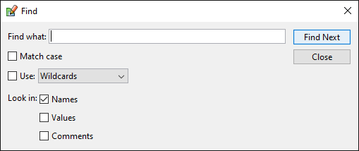 |
The default behavior is to find objects with names that contain the string you type into the find what field. If wildcards is used, the string can contain or ?, where matches one or more characters and ? match one character.
If the Values checkbox is checked, find will look in object properties and make it possible to find objects that have a certain property or objects that contain a specific value.
If the Comments checkbox is checked, find will look in the object comments.
The Find Next command (F3) is a shortcut to select the next matching object.
The Next Error (F4) command looks in the selected configuration and selects the next object that is incomplete or in conflict. It starts searching from the currently selected object or from the beginning of the file if no object is selected.
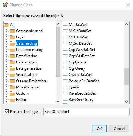
The Change Class command opens the dialog that can be used to change class of an object. The dialog also provides a possibility to Change the name of the object.
View Menu
The Back and Forward commands works very much as you are used to in web browsers, but instead of moving back and forward in the history of web pages, it takes you back and forward in the history of selected objects. The Back command takes you to the previously selected object, and the Forward command takes you forward in the history of selected objects. Back and Forward are available on the toolbar.
The Show Log Window command opens the log window, or brings it to the front if it is already open.
The Show Property Editor command opens the editor panel or dialog if it is closed.
The FloatingDocking Property Editor command floats the property editor if it is docked, and vice versa.
The Small Nodes, Medium Nodes, and Large Nodes commands are applied to the currently selected object, or the currently selected dataflow window if no object is selected. In the former case the nodes in the object's sub-tree are minimized (normalized or maximized), while in the latter case all visible nodes in the configuration are affected. The Node buttons (small, medium, large) on the toolbar perform the same actions.
 |
Tools Menu
The Carmenta Explorer command starts Carmenta Explorer. If a configuration is selected, it is sent to Carmenta Explorer, where it can be inspected and tested. There is a toolbar button (the globe icon) for this action, a shortcut (F5) and it can also be found on the popup menu described in section 5.8.
The Options... command opens the options dialog.
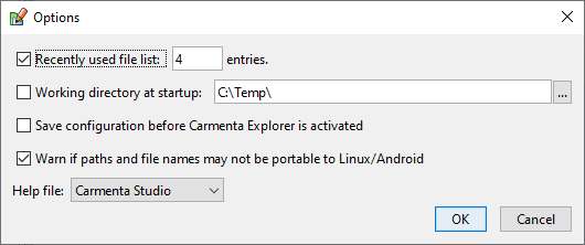 |
In this dialog, you can specify the number of files shown in the list of recently used files, set working directory at startup, tell Carmenta Studio to save current configuration before it is sent to Carmenta Explorer, choose if Carmenta Studio should hide classes that are unavailable and if Carmenta Studio should open the Carmenta Engine SDK documentation instead of the Carmenta Studio documentation.
The "Warn if paths..." checkbox is only shown on Windows. If you check it, Carmenta Studio will show you warnings whenever you specify a path or file name that may not be portable to a Linux or Android device. It will look for backslashes, absolute Windows paths, and even try to compare casing of the file names you specify with the actual names of your geodata files. Objects and properties failing this check will be highlighted in the configuration.
Window Menu
The New Dataflow Window command creates a new dataflow window displaying the active configuration. It is equivalent to dragging the configuration from the object index to the desktop panel or double-clicking on the configuration in the object index. New Dataflow Window is also available in a popup menu for the files in the object index.
The Cascade command divides the desktop space among the dataflow windows such that they are all maximally large while anyone can be moved to the front by a single mouse click.
The Tile Horizontally command divides the desktop in equal horizontal strips, one for each open dataflow window.
The Tile Vertically command is similar to the previous command, but uses the vertical axis.
The Resize to Fit command resizes the currently selected dataflow window to the bounding box of the dataflow diagram.
The Close Other Files command closes all the dataflow windows except the one currently in focus.
The Close All command closes all the dataflow windows.
All of the above commands, except Close Other Files and Close All, are available on the toolbar.
After the above commands, a list with all open dataflow windows follows. These commands can be used to bring a dataflow window to the front.
Help Menu
The User's Guide command shows this document in a web browser.
The Help command shows the documentation of Carmenta Engine. The command is also available on the toolbar, by pressing F1 and by using the help command on the popup menu. The help is context sensitive and tries to take you to the documentation of the object or object property that is selected.
The About Carmenta Studio command displays version information in a dialog window.
Popup Menu for Objects
The menu is shown when you click the right button on an object in a dataflow window or on the object shelf.
The Cut, Cut All, Copy, Copy All, Paste, Delete and Delete All commands are the same as in the Edit menu.
The Remove Reference command removes a single reference to an object, which is usually what you want if the object is a shared item. Remove Reference is only enabled if there is more than one reference to the object. You can see that an object have more than one reference when the name of the object is written using italic style in the dataflow.
The Copy Here command replaces a reference to a shared object with a new copy. This command is only enabled if there is more than one reference to the object.
The Copy All Here command replaces a reference to a shared object with a new copy of the entire sub-tree. This command is only enabled when you right click and drag & drop a node with a sub-tree.
The Open Imported File command appears if the selected object is a reference to an external object. It opens the file that contains the imported object.
The Change Class... command opens the dialog in Figure 20 below. It can be used to change class of an object, e.g. to change a DataSet type. After the class has been changed you must review the properties, in case they need to be updated to be valid for the new class.
 |
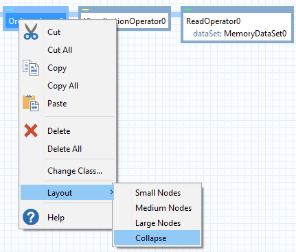
The Layout command opens a menu where you can resize the nodes. The Small Nodes, Medium Nodes and Large Nodes are the same as in the View menu and on the toolbar, and the Collapse command evidently collapses the current sub-tree.
 |
Popup menu for files
The menu is shown when you click the right button on a file in the Objects tab.
The popup menu for files consist of the following commands New Dataflow Window, Close, Close Other Files, Close All, Save, Save As, Save All and the Carmenta Explorer command. They have all but one been described in sections above and the will therefore not be repeated in detail here. The Close Other command is not described earlier, and it closes all open configurations except the selected one.
Object Shelf
The object shelf is the rightmost thing on the toolbar, see Figure 22 below. When it is empty all you see is the drop target, which looks like a lowered square, and two disabled arrow buttons. When an object has been placed on the shelf, its icon and name are displayed next to the arrows, where they can be selected and used as a drag source.
 |
If you select the object on the shelf, the object and its descendants are listed in the Objects index.
You can put several objects (or groups of objects, rather) on top of each other on the object shelf. If the object shelf contains two objects or more, the arrow buttons are enabled. Using the arrow buttons you can walk through the root objects on the object shelf and change which object that is shown.
If you have objects on the object shelf and wish to close Carmenta Studio, do not forget to save the object shelf. Click on the visible object on the shelf and press the save button. The objects on the object shelf will then be saved as a separate .px file which you later can load when you need the objects.
Classes, Resources and Objects
This chapter describes in detail the contents and usage of the three indices in the index pane.
Classes
The class index, Figure 23 below, is used for creating new object instances. It consists of a tree and a list. The list shows all the classes corresponding to the currently selected tree node, in alphabetical order. The tree is organized as follows. There is a single root node labeled All that contains a number of child nodes: Commonly used, Layer, Data reading etc. The Commonly used node provides easy access to the most frequently used objects in a Carmenta Engine configuration. The Miscellaneous node contains simple objects such as colors and strings. The Templates node contains some common templates that consist of several other objects. If the root node All is selected then the list will display all classes and templates available in the current version of Carmenta Engine.
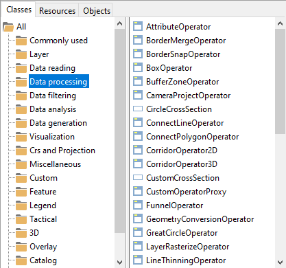 |
To create an instance of a class you simply drag the class from the class index list to a dataflow window and drop it on a matching target. The new object will be assigned the available default values for properties in the class and an automatically generated name.
A Carmenta Engine installation always has a license key that tells which plug-ins that are licensed. In Carmenta Studio, both licensed and unlicensed objects are available, but the unlicensed objects are grayed out in the class list. If you add an object in your configuration for which you don't have a license, it will be marked as an error in the configuration. You will also not be able to view the configuration in Carmenta Explorer.
Resources
The resource index, Figure 24 below, provides access to all known system resources, i.e., predefined objects that always are available in Carmenta Engine. It consists of two lists. The left list contains folders, one for each kind of resource, and the list to the right displays all resources in the currently selected folder.
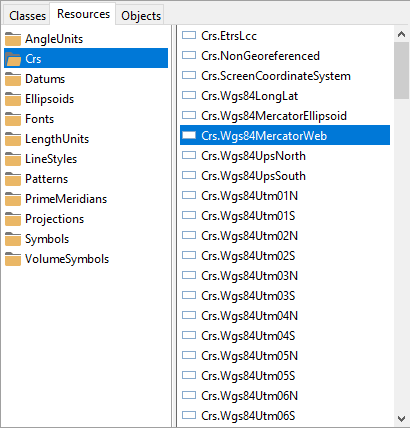 |
If you wish to use a system resource in a configuration, just drag it from the index to the dataflow window. Note that if you repeat the operation, e.g., if you drag a resource to several different locations on the background, you will get multiple references to a shared object. That is, only one external reference to the resource is created.
The Color, Fonts, GeodeticDatums, LineStyles, Projections, Crs and Symbols folders all contains predefined objects ready to be used in your configurations.
Objects
The objects index, Figure 25 below, consists of two lists, a combo box and a text filter. The left list contains all open configuration files, while the right list shows a subset of the objects in the currently active configuration, according to the filter selected in the combo box. The text filter uses entered text to filter out all objects that does not contain the used letter or word (within the result of the combo box filter). It can filter both object and class names, and the list of results can be sorted by both name and class.
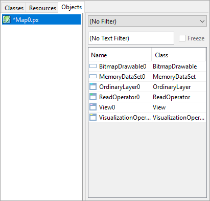 |
The combo box contains two kinds of filters: property filters and class filters. A property filter accepts objects that satisfy a certain condition, such as being public or external. A class filter accepts objects that belong to a certain part of the class hierarchy or belong to a certain plug-in.
Most of the filters are straightforward, but a few need to be explained. "Top Level" means the objects that are roots in the dataflow diagram. "Closure of Selected" means all objects, nodes as well as items, that are referenced in the sub-tree of the selected object. If you copy a sub-tree from one configuration to another, this is the set of objects that will be copied. "Referring to Selected" means all objects that refer directly to the selected object. Most objects have very few references, but some items, e.g., a color or a path string, may be used in many places. Finally, "Similar to Selected" means all objects of the same class as the selected object.
There is one checkbox named "Freeze" next to the text filter. The "Freeze" box can be selected to prevent the list from being updated. For example, if you have chosen the "Referring to Selected" filter and wish to inspect the objects in the list, freezing enables you to select the objects one at a time, which would not be possible otherwise (since the contents would change after every selection).
The active configuration is highlighted in the list of open configurations. Configurations that have been modified are marked by asterisks.
Dataflow Diagrams
The dataflow diagram is the most important view of a configuration for a Carmenta Studio user. In this section you will see how different kinds of objects are displayed in the diagram and learn how direct manipulation of the nodes of a diagram is used to modify a configuration.
A dataflow diagram is drawn as a horizontal tree structure (or forest, since there may be more than one root) with the root at the left edge. There are two kinds of objects in a diagram: nodes and items. The nodes form the backbone of the tree, while the items are drawn below the nodes. An item is associated with a node, or another item. The items and sub-items are indented, which makes the nodes look like small vertically drawn trees.
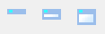
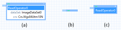
Figure 26 (a) shows an example of a node. The node is surrounded by a colored border with two controls at the top. The control to the left is an icon (a colored rectangle) which is also used to open or close the node. Figure 26 (b) shows the node in its closed state. The control to the right is a plus or minus sign which is used to show or hide the items of the node. Figure 26 (c) shows the node when the items are hidden. If a node has no items, then no plusminus is drawn.
 |
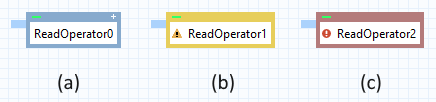
The node border is normally painted light blue if the node or one of its items is selected; see Figure 27 (a). If a node is incomplete, i.e., has an undefined property or some other warning, then the border is painted yellow, as in Figure 27 (b). A warning sign is also shown at the object where there is something missing. If there is a type conflict or another severe error, then the border is painted red, as in Figure 27 (c). The state of the items also influences the border color. If there is something wrong with an object it is marked with a red circle with a white exclamation mark.
 |
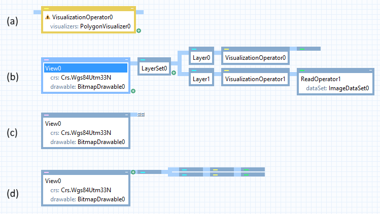
The connections between nodes are drawn as thick light blue lines. The joint areas are used for three purposes besides showing the tree structure. First, they act as a visual signal when a node lacks a parent or a child, as in Figure 28 (a). Second, they are used as expandcollapse controls for sub-trees. Figure 28 shows a tree before (b) and after (c) a mouse-click in the joint area. There are two different ways to expand a sub-tree: (i) by clicking in the joint area, the sub-tree will go back to its previous state; (ii) by clicking on the icon representing the collapsed sub-tree, all nodes in the sub-tree will be expanded and closed. Figure 28 (d) shows the effect of clicking on the sub-tree icon. Third, joint areas are highlighted to provide visual feedback during drag and drop operations.
 |
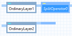
Configurations aren't really tree structures. The objects actually form a directed acyclic graph where the items often have more than one parent. Certain nodes, such as SplitOperator, may also have more than one parent. Carmenta Studio allows multiple references to nodes, but it doesn't draw a sub-tree more than once. If there are two or more references to a node, then the first (topmost) will be drawn as an ordinary sub-tree, while the others will be drawn as references (closed nodes without any controls), as shown in Figure 29.
 |
Items may be placed at the top level, directly on the background. Such items are drawn without a colored border, as illustrated in Figure 30.
 |
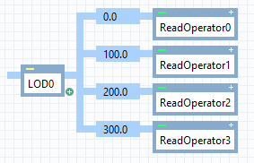
Another special case is the LevelOfDetail node which is drawn simply as a number directly on the joint area, as shown in Figure 31.
 |
The remainder of this section describes some common use cases for direct manipulation of dataflow diagrams.
Adding new nodes
The easiest way to add new nodes is to use the  that appear at the bottom right of nodes and in the value cell in the property grid.
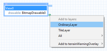
For example, to add a new layer to a View node, click the button at the bottom right and choose to add a new Layer or start the "Create Layer for Data File" wizard.
 |
Move
The gesture for a move operation is simple: press the left mouse button while the cursor is over the object, drag it to the new location, and release the left button.
The items and sub-items of a node or item always move together with the node object. The node children (sub-tree) of a node move with the parent unless Carmenta Studio can detach the node, e.g., remove it from an operator chain. If the Shift key is pressed during the operation, then the sub-tree is always moved.
During a move operation the cursor changes when the cursor is over a matching target, and the target is highlighted. Items can be dropped on nodes or other items. Nodes can be dropped on other nodes or in joint areas. All objects can be dropped on the background. When the target is a list of nodes (or the top level), the insertion point is indicated by a small arrow.
The footer line displays the matching target or targets. If there is more than one matching target, i.e., several matching properties, then a popup menu is shown when the left button is released. To cancel a move operation, drop the source on itself or on any illegal location, or click outside of the popup menu.
Objects can only be moved within a configuration, not from one configuration to another.
Copy
Keep the Ctrl key pressed during a drag and drop operation if you wish to copy rather than move the source object. Also press the Shift key if you wish to copy a sub-tree rather than a single node. Except for these modifier keys, a copy operation is like a move operation. Items are always shared, not copied, except for the source object itself if it is an item.
Objects may be copied from one configuration to another. Carmenta Studio tries to replace items in the copy by equivalent items in the target configuration to maximize the reuse of shared resources. For example, if you make two copies of the same sub-tree, then the copies will share all items.
References
The Alt modifier key is used to creating references to existing objects. The most common case is when you wish to reuse a shared item within a configuration, but it is also possible to create references to public objects in other configurations. If you add such an external object reference to a configuration, then Carmenta Studio will include the necessary import statement in the file.
Right button Drag and Drop
When you do a drag and drop with the left mouse button, the operation that is performed is controlled by the use of modifier keys. If you instead do a drag and drop with the right mouse button pressed, the operation that is performed is selected from a popup menu that is shown after the drop. The content of the popup menu depends on the source and target objects of the drag and drop operation. The following commands can appear in the drop popup menu:
The Move Here command performs as the name suggests a move operation. It is equivalent to a drag and drop using the left button without modifiers.
The Move All Here command performs as the name suggests a move operation. It is equivalent to a drag and drop using the left button with the Shift key pressed, which will move all objects in the sub-tree.
The Copy Here command corresponds to a left button drag and drop with Ctrl key pressed.
The Copy All Here command corresponds to the left button drag and drop with Ctrl and Shift keys pressed.
The Create Reference Here command corresponds to a left button drag and drop with the Alt modifier key pressed.
The Create Object Here command appears if you drag an object from the class index.
The New Dataflow Window appears if you drag a configuration from the file list to the desktop panel.
The Cancel command can be used to cancel the drag and drop operation. Another way to cancel the operation is to click outside the popup menu.
Object Editors
Carmenta Studio has a handful of standard object editors for different kinds of objects, and support for integrated custom editors. The editors occupy the same area of Carmenta Studio (which means that only one of them is visible at a time). The editor panel normally resides below the index pane, but it can also be floated in a dialog frame of its own. When in floated mode, it can be closed by pressing a button in the upper right corner and reopened by choosing Show Property Editor from the View menu.
 |
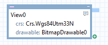
The standard editors have a common toolbar with two controls that are always visible. Figure 33 shows the toolbar. The button to the left, which looks like a post-it, invokes a comment editor on the selected object. All objects can have a comment attached to it. An object with a comment gets a similar post-it icon in its upper right-hand corner, in the dataflow diagram, see Figure 34. The comment for an object will be displayed as a tooltip when the mouse hovers over the object. The second button shows the help section for the class.
 |
The properties editor for objects is shown in Figure 35. To the left of the toolbar is the name of the class written with a link to the class page.
The first row in the properties editor contains the name of the object. The second row contains a modifier that is used to specify the public flag. To be able to create a reference to an object in another file, the object has to be declared public in the file where it is defined.
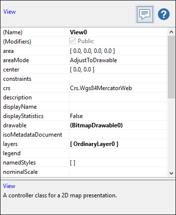 |
The properties editor has two columns and one row for each property of the object. You can select one or more rows of the table. The left column shows the property name and the right column shows the property value. Properties not set to a specific value are written with default values using normal style and properties with changed values area written using bold style. If a property is set to its default value, it is written using bold and italic style.
The cells in the Value column is most often simple text fields, but for certain types, it contains a drop down list or an editable combo box. Drop down lists are used for enumeration properties where valid values can be selected from the list.
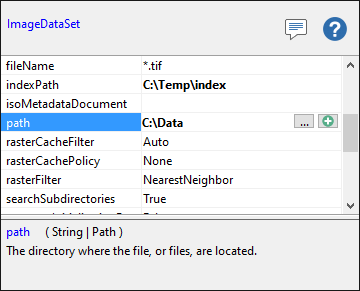
If the type of the property is a class, the name of all objects available in the configuration file and from the system resources are selectable from a combo box. For example, when you edit the Crs property of a View (Figure 36), the drop-down list contains all predefined reference systems (those in the Crs folder in the Resource index, Figure 24). The list would also contain all reference systems you may have created elsewhere in the configuration (you may have dragged an instance of the Crs class from the Carmenta Engine Crs folder of the Class index, Figure 23).
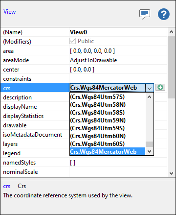 |
Property values can be edited directly in the value field in the properties editor, or they can be edited in a custom editor or sometimes a text editor. There are several ways to open these editors. If no custom editor is available, you have to edit the property on the current row.
You can see that a property has a custom editor when the custom editor button is visible in the property value field, as in Figure 37. You can open the custom editor by pushing the button.
 |
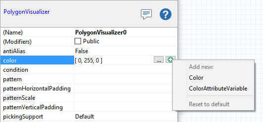
You can also insert new matching items or references to existing items by
clicking the "Add Item" (![]() )
button, as in Figure 38.
)
button, as in Figure 38.
 |
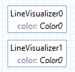
When you are changing a property value in the object editor, it is important to note the difference between a value for that property and a value for a named object in that property. If you name for instance a color, and use it as a background color for a window, you can reuse that color in other objects as well. This means that the object (that has been given the name TaxiYellow), will change at all locations where you are using it, just by altering the color at one place. If the color not is a named object, the change will only apply to the property where you perform the change. Figure 39 shows the difference between a named object and an unnamed color as appearing in the dataflow window nodes and in the object editor.
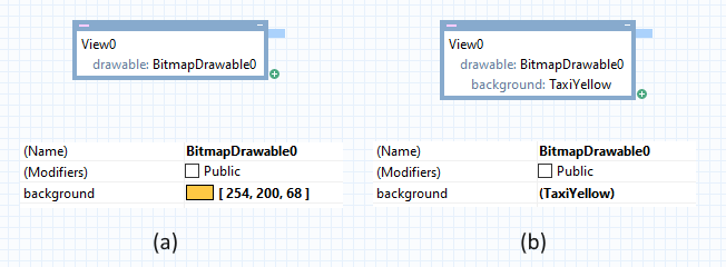 |
In Figure 39 (a) the color is not a defined object, which means that all changes will apply to only Window0, but (b) has the defined object TaxiYellow as color. Therefore changes to the object TaxiYellow will apply to all places where you have used the object.
Special editing support for "known" user properties
For most classes, you can see some additional properties at the bottom of the property editor under the heading Catalog user properties:
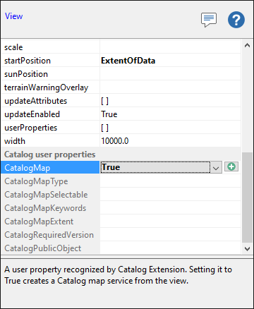 |
These are in fact user properties of the kind that is normally edited through the userProperties property. However, Carmenta Studio knows about user properties that the Catalog mechanism and Carmenta Server use, and offers an easier and less error-prone way to edit these, instead of going through the userProperties property.
Note that these special editing capabilities can not be used if userProperties references a named AttributeSet instance.
Configuration editor
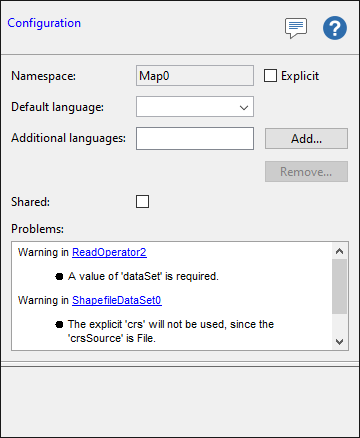
Figure 41 shows the configuration editor. This is displayed when you click the background of the data flow window. It has a text field and a check box at the top, a few controls for specifying languages, a Shared check box, and a text area at the bottom.
The namespace field defines the namespace used for resource objects. The default value for the namespace is the same as the filename. If you want to set the namespace to another value, check the Explicit check box and write the namespace name in the namespace text field.
You should normally not check the Shared box. It affects what happens if an application loads the configuration multiple times, and can be used to avoid creating several copies in memory of the same objects. If checked, Carmenta Engine will keep a copy of the configuration in memory, and if the same file is requested again, the same copy will be returned.
For an explanation of the language controls, please see Language support and localized properties below.
The text area is read-only and displays a list of errors and warnings present in the configuration, with links to the corresponding nodes:
 |
Language support and localized properties
Some classes have localized string properties that can be specified in multiple languages, for instance the display name and description properties of layer classes. If a property is specified in several languages, the application displaying the map may let the user select one of the languages, and perhaps show a layer control with display names in the selected language.
To add language support to a configuration in Carmenta Studio, you need to do a few things. First, in the configuration editor shown when you click the background of the data flow window, you should specify the default language for the configuration. This is the language used for the default localized properties, like Layer.DisplayName. In addition to this you may add one or more additional languages, by pressing the Add button in the configuration editor. The following figure shows the configuration editor with English selected as the default language, and German and French added as additional languages:
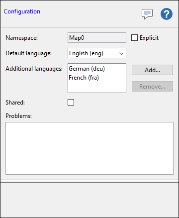 |
Languages are identified by strings. The drop-down menus contains some common languages, but you can enter any language string you want. It is recommended though that you use the three-letter language codes from the ISO 639 standard.
So far you have only specified which languages you want to support. So where do you specify the actual strings for the localized properties? Well, after you have added some languages to the configuration, go back and select for instance an OrdinaryLayer, and look in the property editor. You should now see that the localized properties have separate entries for each language:
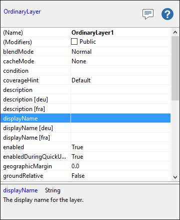 |
In the figure above, the displayName property is still there, and now specifies the display name in the default language, i.e. English. But there are also two new entries, displayName [deu] and displayName [fra], where you can enter the German and French strings.
Carmenta Studio will generate warnings if you specify a localized property in one or more, but not all languages. The reason for this is that you should be able to add a new language, and then easily find all properties that you need to specify in the new new language, without risking forgetting some of them.
Languages are important if you want to publish the configuration file with the Catalog mechanism. One catalog service will be created for the default language and one for each additional language. If the default language is not specified, the corresponding catalog service will have an empty language specifier. If the default language is set to "None", no service will be created for the default language.
Custom Editors
There are custom editors defined for some of the utility objects. The purpose of the custom editors is to hide the syntax for complex objects so that you can spend less time tweaking with the syntax when you create your map configurations.
As described in the previous section, you know that a custom editor is
available when the  button is visible in the value
column of editor tables. You can also choose "Edit in custom editor" from the
popup menu or just double click on the property in an editor table.
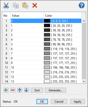
In all custom editors that contain tables, the following buttons are found:
button is visible in the value
column of editor tables. You can also choose "Edit in custom editor" from the
popup menu or just double click on the property in an editor table.
In all custom editors that contain tables, the following buttons are found:
 |
The first button is used to add new rows to the table. The second button is used to delete the selected rows. The remaining buttons are used to move all selected rows up or down in the table.
Color Editor
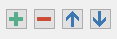
Colors can be edited using the custom editor in Figure 45. The editor has three tabs in which the color can be specified in three different ways. In the lower part of the color editor the transparency can be specified.
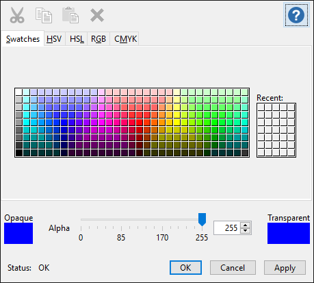 |
ColorTable Editor
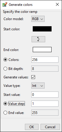
ColorTables are used to specify how raster values should be translated to colors. In Figure 46, you see the color table editor in the object editor area. The table has two columns, one for raster values and one for the colors. The table supports cut, copy, paste and delete. The "Generate Ramp...' button opens a dialog that is used to generate a color ramp as in the figure. In the color ramp dialog you specify start color, end color and the number of colors. It is optional to generate values. If you want to generate values, you can specify start value and how much the value should increase for each new color.
 |
To work properly when used in Carmenta Engine, the values in the table needs to be sorted. The Sort button takes care of that.
The color ramp dialog used to generate the color ramp in Figure 46 is shown in Figure 47.
 |
AttributeVariable Editors
AttributeVariables are used for many properties of Visualizers and for properties for some Operators. They can, as described in the documentation for Carmenta Engine, be defined in one of five ways:
Direct: just a fixed value.
Indirect: the value is retrieved from a specified feature attribute.
Expression: the value is the result of evaluating an expression that may refer to feature attributes.
Keyed: a value, retrieved from a feature attribute, is used as a key in a lookup table to get the final value.
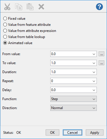
Animated: a value that can vary with time - this way is possible only for a value of type Color or Double.
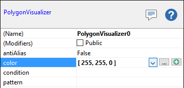
AttributeVariables are used for different types (Color, Font, Int, Double, String, LineStyle, Symbol, etc.), but the editors look the same. Figure 48 shows how the AttributeVariable editor is used to specify a direct value for the color property of a SymbolVisualizer.
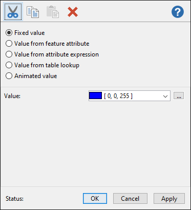 |
Figure 49 shows how the AttributeVariable editor is used to specify an indirect value for the same color property.
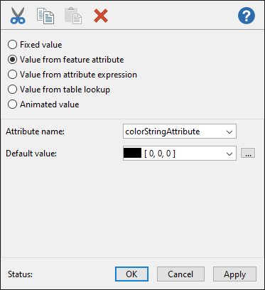 |
The Attribute name drop-down list contains all built-in update attributes and, if the AttributeVariable is part of a Visualizer or Operator connected to a DataSet, it will also contain attributes that exist in the source DataSet or have been set by Operators in the operator chain.
Figure 50 shows how the AttributeVariable editor is used to specify a value that results from evaluating an expression that references feature attributes.
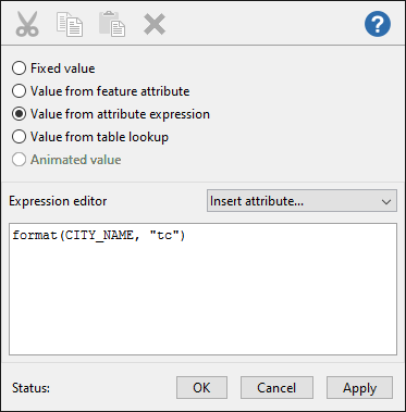 |
The Insert attribute drop-down list contains all built-in update attributes and, if the AttributeVariable is part of a Visualizer or Operator connected to a DataSet, it will also contain attributes that exist in the source DataSet or have been set by Operators in the operator chain.
Figure 51 shows how the AttributeVariable editor is used to specify a keyed value.
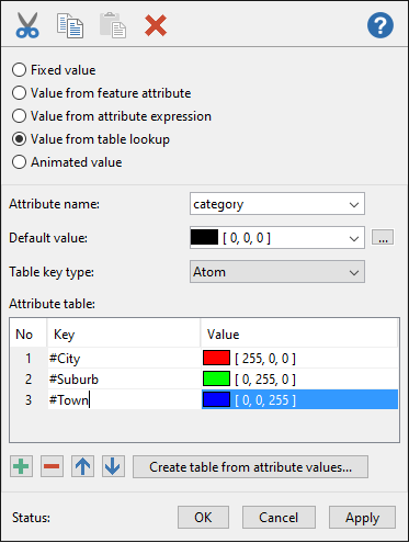 |
The  button can be used
to create the table automatically. However, this only works if the
AttributeVariable is part of a Visualizer or Operator that is connected
to a DataSet (since the data must be inspected).
button can be used
to create the table automatically. However, this only works if the
AttributeVariable is part of a Visualizer or Operator that is connected
to a DataSet (since the data must be inspected).
Figure 52 shows how the AttributeVariable editor is used to specify a Double value that varies with time. For more details, see Animated Visualization.
 |
Condition Editor
A Visualizer (or a FilterOperator) uses a condition to decide if it should be used to visualize a feature. Conditions are also used for the layer's condition property which controls a layer's onoff state based on user-definable "update attributes". A condition entry must evaluate to true for the condition to be met.
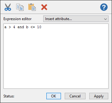 |
The Insert attribute... drop-down list can be used to insert built-in update attributes and attributes that exist in the source DataSet, or that have been set by Operators in the operator chain, into the condition.
Font Chooser
The Font Chooser is used to specify a font name for a Font object. The user specifies the font name, size, if it should be bold or not and if it should be italic or not. The result is a font name in the syntax used in Carmenta Engine. Note that in Carmenta Engine font size is specified in pixels, not points as in many other programs.
 |
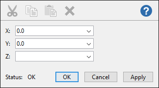
Point Editor
The Point Editor is used to specify the x, y and optionally z values of a point.
 |
Points Editor
The Points editor is used to edit several Points, e.g. the points of a Polygon or LineGeometry defined in the configuration file.
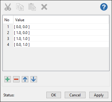 |
String Editor
The String Editor is primarily used to edit multi-line string contents.
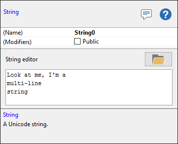 |
By using the "Insert path" button  in the string editor,
you can easily insert a path to a file or a directory.
in the string editor,
you can easily insert a path to a file or a directory.
However, a short single-line string may be easier to edit directly in the property grid:
 |
Custom List Editors
Apart from the custom editors shown above, Carmenta Studio contains a number of Custom List Editors for lists of different kinds of objects. They all look and work like the Conditions Editor or Points Editor above.
Utility objects
Carmenta Studio contains some utility objects not found in the Carmenta Engine object model: Bool, Color, Double, ColorTable, Comment, EnvironmentVariable, Int, Path, RegistryValue, String.
The simple utility objects Bool, Color, Double, Int and String will be converted to their native representation in each API.
A ColorTable is used as part of a RasterVisualizer in Carmenta Studio, but it will be converted to a keyed attribute variable that returns a color.
An EnvironmentVariable or RegistryValue will be looked up and replaced by its value, usually a String.
A Path object in Carmenta Studio will also be converted to a String.
The utility object Comment is used to add comments about an entire configuration or parts of it. It is useful for instance when several persons are working on the same configuration, to add information about what has been done and what is planned to do.