Properties of the Sensor
Here is an overview of the physical properties of the sensor; they are controlled by operator properties that are attribute variables which means that they can be dynamically set from attribute values of features read from the observerInput (see LineOfSightOperator.ObserverInput and VisibilityIndexOperator.ObserverInput). These observer properties are available in all operators derived from VisibilityOperator, with some exceptions that are explicitly noted.
Where is the sensor?
The sensors are located at the positions of one or more observers that comes from the observerInput of the operator.
Horizontal position
A LineOfSightOperator can accept both points and lines from the observerInput.
If a point comes, its x and y coordinates gives a single sensor position.
If a line comes, the LineOfSightOperator will compute the regions that are visible when the observer moves, in a straight line, from the first to the second point of the line.
A TargetLineOfSightOperator and an AirspaceCoverageOperator can accept only points from the observerInput.
A VisibilityIndexOperator accepts only polygons from the observerInput, each specifying a region where we want to calculate visibility indexes for a possible observer. Each terrain cell inside the region is used as the horizontal position of the observer, to compute the visibility index for the cell.
Vertical position
The vertical position of observers in VisibilityIndexOperator is determined by the VisibilityOperator.SensorHeight and the VisibilityOperator.ObserverHeightType.
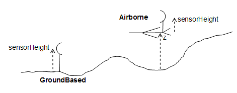
LineOfSightOperator, TargetLineOfSightOperator and AirspaceCoverageOperator are a little more complicated since they have a the property LineOfSightOperator.CarrierType, which can be either GroundBased (default) or Airborne.
When the LineOfSightOperator.CarrierType is GroundBased, the z coordinate of an observer input feature is ignored, and the sensor is assumed to be VisibilityOperator.SensorHeight above ground.
When the LineOfSightOperator.CarrierType is Airborne, the sensor is assumed to be VisibilityOperator.SensorHeight above an airborne carrier, whose height is given by the z coordinate. The meaning of z is given by the property VisibilityOperator.ObserverHeightType.
 |
What size and shape has the sensor lobe?
The maximal range of the sensor is given by the property VisibilityOperator.MaxDistance, which is interpreted in different ways:
in VisibilityIndexOperator: a horizontal distance,
in LineOfSightOperator, TargetLineOfSightOperator and AirspaceCoverageOperator: the meaning depends on the property maxDistanceType, which may be Horizontal or ThreeDimensional.
The VisibilityIndexOperator does not have any more range properties, but the other three operators have two more: the maxUpDistance and the minDistance. The minDistance has somewhat different semantics in the operators that support it:
in LineOfSightOperator, the minDistance is interpreted as a horizontal distance for an observer that is a point, but ignored for an observer that is line.
in TargetLineOfSightOperator and AirspaceCoverageOperator, the minDistance is interpreted as a three-dimensional distance.
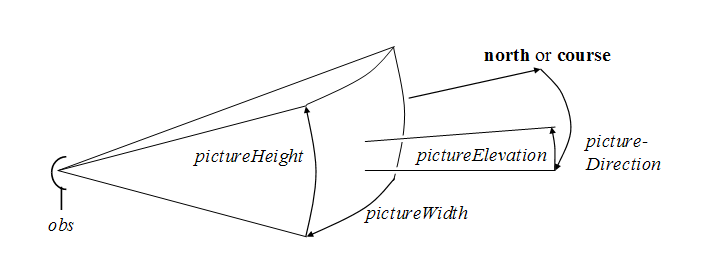
A sensor may not be able to see in all directions, so you can define a sensor lobe with a rectangular cross-section. Its angular width is given by VisibilityOperator.PictureWidth; its angular height is given by VisibilityOperator.PictureHeight. The central horizontal direction is given by VisibilityOperator.PictureDirection; the central elevation angle is given by VisibilityOperator.PictureElevation. The figure gives a 3D image of the lobe, seen from the side.
 |
All angles are given in degrees. The pictureElevation is measured upwards from horizontal. The pictureDirection is measured clockwise from a zero direction, which is north when the observer position is a point, but the course when the observer position is a line.
This lobe description is, in fact, ambiguous: the exact shape of the lobe depends on the boolean property VisibilityOperator.VerticalRotationAxis. Briefly, the property should be True (default) for a mechanical radar system with a vertical rotation axis, and False for a camera with a fixed orientation.
A phased-array radar system has a range that varies with the direction. To model such a radar system, you can let the property VisibilityOperator.DistanceVariation be PhasedArray, rather than its default Constant.
If verticalRotationAxis is True, and you want two equally sized sensor lobes in opposite directions, you can set the property VisibilityOperator.SecondPictureBackwards to True. This is mainly useful for a phased-array radar system.
Refraction in the atmosphere
Light rays and microwaves normally bend downwards, due to refraction in the atmosphere. How much they bend depends on the wavelength, the weather, and the altitude. In the visibility operators, the bending is controlled by the property VisibilityOperator.Refraction. Its default value is 1.25, but we suggest that you use 1.33 for radar systems and 1.15 for visible light, unless you know better values.
Previous: VisibilityIndexOperator: from where do I see best?
Up: Visibility Analysis
Next: Overlapping Viewsheds