Basic 3D Map Application Tutorial
In this tutorial you will learn how to show a 3D view together with a 2D view using the same data.
Before you start, ensure that you have complete installations of Microsoft Visual Studio 2022, Carmenta Engine 5 SDK and Carmenta Engine Samples Geodata.
The result of this tutorial is also included as a sample application in the Carmenta Engine SDK.
Step 1: Add a 3D view
This sample uses the result from the Basic Map Application Tutorial. Make a copy of that entire sample, and then open the solution file from the copy.
Start by going to the Design View of the main form. Add a new Panel for the 3D view:
Add a SplitContainer to Panel2 of splitContainer1.
Set the property Orientation to Horizontal.
The 2D view will be in the upper part of this SplitContainer and the 3D view in the lower part. Adjust the splitter so that the two panels are of equal size.
Switch to the code view. The MapControl that currently exists is the 2D view and it is set to the panel of the first SplitContainer. Change the code to:
splitContainer2.Panel1.Controls.Add(mapControl_);
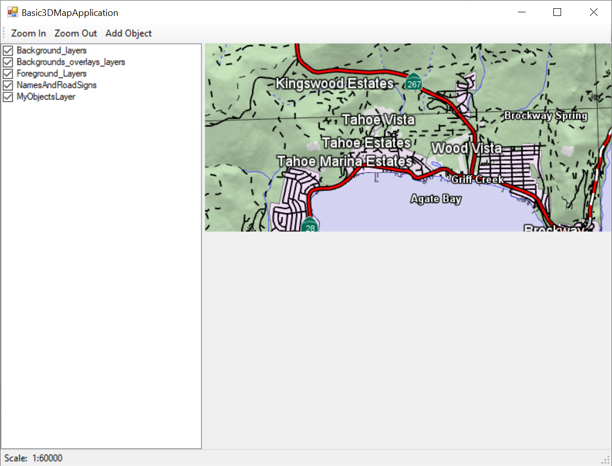
Start the application and make sure that the 2D view is shown in the upper part of the right panel. It should look like this:
 |
A new MapControl is needed for the 3D view. Before you add it to the application a 3D view in the configuration is needed. In the Sample Map Configurations folder you can find the configuration "3d_tahoe.px". Open the configuration in Carmenta Studio and copy LakeTahoe3D to the configuration in the Basic3DMapApplication solution called "basic_map_application.px". This can be done by having both configurations open in Carmenta Studio followed by right clicking on the LakeTahoe3D and drag and drop into the other configuration. In the context menu that appears, choose "Copy All Here". Save the configuration but don't close Carmenta Studio, as you will make some additional modifications later in this tutorial.
Now that there is a 3D view in the configuration, it can be added to a MapControl.
Add another MapControl called "mapControl3D_" and initialize it.
Set the Dock property to DockStyle.Fill
Add it to Panel2 of splitContainer2.
Set its view to the view you added to the configuration by adding the code
mapControl3D_.View = configuration.GetPublicObject("LakeTahoe3D") as GlobeView;
The 3D view needs a tool to navigate with. In this tutorial we continue from an already created 2D view and the purpose is to show how the same area can be visualized with a 3D view. The views will share the same data but will be interacted with independently. If your aim is to have a 3D view and then use a 2D view just for assisting the navigation of the 3D view you should consider the OverviewTool for the 2D MapControl. The topic will not be covered in this tutorial but you can find information in the documentation. Now we will create a StandardTool3D for interacting with the map:
Add a StandardTool3D as a member variable to Form1:
StandardTool3D standardTool3D_;
At the location of the code that instantiates and adds a StandardTool to the 2D view, instantiate the StandardTool3D and add it to the mapControl3D_ member variable:
standardTool3D_ = new StandardTool3D();
mapControl3D_.Tool = standardTool3D_;
With the StandardTool3D you can:
Pan the map by holding down the left-button and dragging the mouse.
Zoom in/out towards the point of the mouse cursor by holding down the right-button and moving the mouse forwards and backwards.
Rotate around the point of the mouse cursor by holding down the middle button and moving the mouse left or right.
Rotate the camera by holding down CTRL and dragging the mouse.
The GlobeView loads the ground tiles asynchronously on background threads.
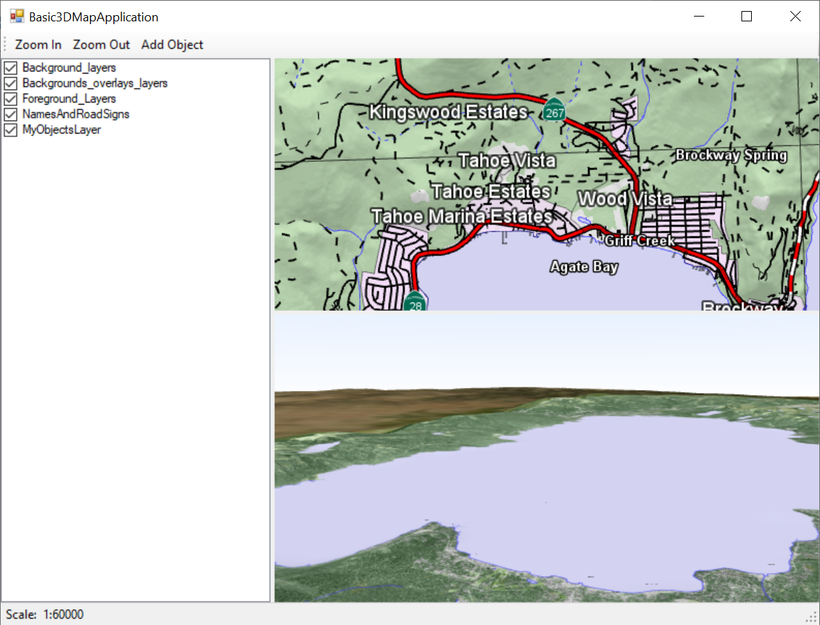
Start the application. You should now have both a 2D view and a 3D view visible, showing Lake Tahoe. Try out the StandardTool3D features mentioned above. It should look like this:
 |
Step 2: Add the application layer to the 3D view
The next step is to add an application layer to the 3D view, showing the same objects that we add in the 2D view. We'll be using a 3D model of a helicopter to visualize the added objects in the 3D view.
Add the application layer and create visualizers:
In Carmenta Studio, locate "MyObjectsLayer" in the 2D view and copy the layer to the bottom of the 3D view layers. Note that the dataset is in italic letters, which means it is a reference. If you select it you will see that it is also highlighted in the 2D view layer. You will also see that the two visualizers are references. We want different visualizers for the 3D view, so right click on these and click "Remove Reference".
To visualize a 3D model, add a SymbolVisualizer to visualizers of the VisualizationOperator. Then add a Symbol3D to the SymbolVisualizer. The model is supplied in the "res" folder in the Carmenta Engine Samples Geodata. Edit the Symbol3D by doing the following:
Set the name to "Helicopter"
Set aheadVector to [ 0.0, 0.0, 1.0 ]
Set upVector to [ 0.0, 1.0, 0.0 ]
Set filename to "B212_MIL.flt"
Create a new Path object and set it for the Symbol3D's path property.
Select the "parts" property on the Path object and click on the plus symbol and with "Add reference", choose GeoDataRoot.
Now click on the "..." button and add two entries using the plus symbol.
Name the first new entry "res".
Name the second entry "B212".
You should now have a Path object referencing the "res/B212" folder in the Carmenta Engine Samples Geodata.
When zoomed out it will be hard to see the helicopter due to it being modeled in a realistic scale. A text visualizer will help locating objects in the 3D view:
Add a TextVisualizer to visualizers of the VisualizationOperator.
Set alignX to Middle
Set color to [ 255, 204, 102 ]
Set font to a new Font object with the fontName set to "Arial-18-bold-normal"
Set haloColor to [ 0, 0, 0, 170 ]
Set haloWidth to 2.0
Set offsetZ to 7.0
Set text to "Value from feature attribute" and set the attribute name to "name"
Now the text will show us where the helicopter is even if the model is too far away to be seen. We can also add a InteractionVisualizer to show where the helicopter is relative to the ground.
Add an InteractionVisualizer to visualizers of the VisualizationOperator.
Add a LineVisualizer to the leadLineVisualizer property.
Set color to [ 255, 255, 255, 203 ]
Set style to LineStyles.dashes1 by using Add reference.
Set width to 3.0
This will draw a dashed line from the helicopter down to the ground. You can also add a symbol that is placed at the ground below the object by using the groundNodeVisualizer, but we will skip that for this tutorial.
However, these visualizers will not display anything yet. The problem is that the created objects get a Z coordinate of zero, the sea level altitude, so they are below ground. As the objects will represent helicopters, we'll want the Z value to be 100 meters above the ground.
Step 3: Create objects above the ground
The dataset containing elevation data can be asked for the elevation given an X and Y coordinate. First we need a reference to the dataset in the code, but to access the dataset it has to be set to Public in the configuration. Find the "ElevationBIL" dataset in the 2D view and check the Public modifier checkbox. Remember to save the configuration.
Add the code:
Carmenta.Engine.DataSet terrainHeightDataSet_;
Then, where the views are fetched from the configuration, add the following code:
terrainHeightDataSet_ = configuration.GetPublicObject("ElevationBIL")
    as Carmenta.Engine.DataSet;
In the method OnFeatureCreated, replace the point inside the PointGeometry of the newly created Feature by replacing it with a copy where the Z value has been modified by calling "terrainHeightDataSet_.TryGetValueAt(...)". Also add an extra 100 meters to position the object 100 meters above the ground. Since we are modifying a feature which has been inserted into a dataset, we must take a guard on the MemoryDataSet. We will also need to update both views. The OnFeatureCreated method could now look like this:
private void OnFeatureCreated(object sender, FeatureCreatedEventArgs args)
{
    using (Guard g = new Guard(memoryDataSet_))
    {
        PointGeometry pointGeometry = args.Feature.GetGeometryAsPoint();
        Carmenta.Engine.Point initialPosition = pointGeometry.Point;

        double newElevation = 0.0;

        int terrainHeight;
        if (terrainHeightDataSet_.TryGetValueAt(initialPosition, out terrainHeight))
            newElevation = terrainHeight + 100.0;

        pointGeometry.Point = new Carmenta.Engine.Point(initialPosition.X, initialPosition.Y, newElevation);
    }

    // Update the views
    this.mapControl_.UpdateView();
    this.mapControl3D_.UpdateView();

    mapControl_.Tool = standardTool_;
    toolStripButton3.Checked = false;

    // Increment object number in the name attribute for the next object
    attributeSet_[nameAtom_] = "Object " + objectNumber_++;
}
Try it out. Add an object to the 2D map, and notice that it is added in the 3D map as well.
We want to be able to create objects by clicking in the 3D view as well. The same OnFeatureCreated event handler can be used with a CreateTool3D as well.
Add a CreateTool3D member variable and initialize it with the same parameters as the existing CreateTool (the MemoryDataSet and the AttributeSet).
The CreateTool3D will set the height of newly created objects to the terrain height automatically. It also has an Offset property to adjust the height on creation. After initializing the tool, set the offset property to 100 (meters) to match the 2D view.
At the end of the constructor for Form1, add the OnFeatureCreated event handler to the CreateTool3D, just like for the 2D CreateTool. The code in the constructor to instantiate the tool, add the handler and the offset should look something like this:
CreateTool3D createTool3D_;
createTool3D_ = new CreateTool3D(memoryDataSet_, attributeSet_);
createTool3D_.FeatureCreated += OnFeatureCreated;
createTool3D_.Offset = 100.0;
In the handler for the "Add Object" button, toggle the 3D tools as well. The code should be:
private void toolStripButton3_Click(object sender, EventArgs e)
{
	if (toolStripButton3.Checked)
	{
		mapControl_.Tool = createTool_;
		mapControl3D_.Tool = createTool3D_;
	}
	else
	{
		mapControl_.Tool = standardTool_;
		mapControl3D_.Tool = standardTool3D_;
	}
}
Lastly, we make some modifications to the OnFeatureCreated method. Since the CreateTool3D sets the height of the newly created objects by itself, we can surround the code which sets the height with an if clause that checks if the event originated from the 2D CreateTool. We also toggle back to the StandardTool3D in the 3D map:
private void OnFeatureCreated(object sender, FeatureCreatedEventArgs e)
{
    if (sender is CreateTool) {
        using (Guard g = new Guard(this.memoryDataSet_))
        {
            PointGeometry pointGeometry = args.Feature.GetGeometryAsPoint();
            Point initialPosition = pointGeometry.Point;

            double newElevation = 0.0;

            int terrainHeight;
            if (terrainHeightDataSet_.TryGetValueAt(initialPosition, out terrainHeight))
                newElevation = terrainHeight + 100.0;

            pointGeometry.Point = new Point(initialPosition.X, initialPosition.Y, newElevation);
        }
    }

    // Update the views
    mapControl_.UpdateView();
    mapControl3D_.UpdateView();

    // Toggle back to the Standard Tools
    mapControl_.Tool = standardTool_;
    mapControl3D_.Tool = standardTool3D_;
    toolStripButton3.Checked = false;

    // Increment object number in the name attribute for the next object
    attributeSet_[nameAtom_] = "Object " + objectNumber_++;
}
Try out the application and make sure that you can create objects by clicking in both the views, and that the same objects are visible in both views.
Congratulations! You have now added a 3D view to a 2D view with a shared dataset that can be interacted with and learned how to visualize objects using 3D models.
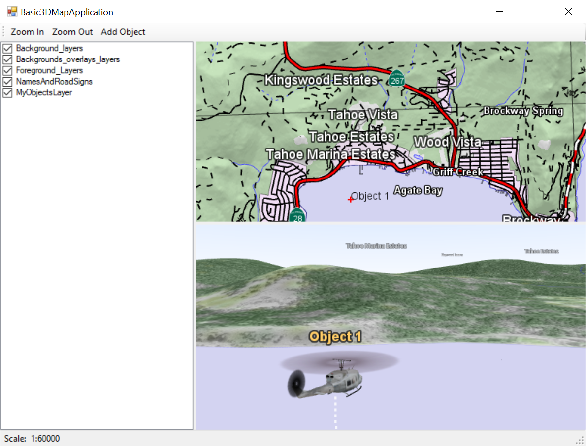
Your final application should look something like this:
 |